| Process: VJ1580 Installation | Ref: VJ1580 User Operation Manual / Service Manual | ||
| prod ucti on proc esse s | operatonal process | Quality & safety focus | Important pictures |
| 1 | Meet with the customer manager | Installation notification content must be ——communication | |
| 2 | Open the box for inspection, check the accessories according to the invoice, and sign for recovery | Use the dispensing tool and no other tools. | |
| 3 | Confirm the installation location | The production line is relatively smooth, as clean or dry as possible. With enough maintenance space, and ventilation | |
| 4 | Install the nozzle bracket | ||
| 5 | Place the machine flat on the operating table | Inked machines, or those in operation, cannot be tilted down | |
| 6 | Check the ground wire and power supply, and connect the power cord | Check the power supply within 220 (110VAC) ± 10%, note the position of the fire wire zero line. Ground resistance is less than 4 ohms | |
| 7 | Check that the circuit board and the connector are firmly connected | ||
| 8 | Check whether the joints of the ink road system are connected normally | Focus on checking the pipeline connection block, atmospheric balance pipe | |
| 9 | According to the ink manual, reconfirm whether the current ink is suitable to the customer material | ||
| 10 | Install customer customized workflow files (ignore this step if random) | Insert U disk with customer custom workflow, Tools> Software Download> Install Workflow Module, Install. | |
| 11 | Export the PRI files to the U disk. | Insert the engineer’s carry U disk, Tools> Software Download> Spray printer information, export PRI documents to the U disk. After the whole machine installation, upload the PRI document to wfx.vid eojet.com | |
| 12 | Close the nozzle cover and check for positive pressure (if configured) | The check-out positive air pressure value was 12-16 scfh. The working sound of the positive pressure pump and the flowing sound of the nozzle positive pressure can be heard | |
| 13 | Put the ink cartridge and solvent into the corresponding slot to perform the update ink. | Tools> Diagnostic> Ink System> Ink, perform the Update. Check the liquid level of the ink and the solvent. | |
| 14 | Check nozzle type, throat length and diameter of viscosity lumen | Tools> Engineering> Product Settings (Production Setup), check and spray The mouth type, throat length, and viscosity cavity limiting block diameter (1.550) were set correctly | |
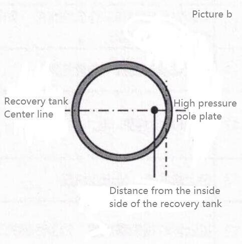
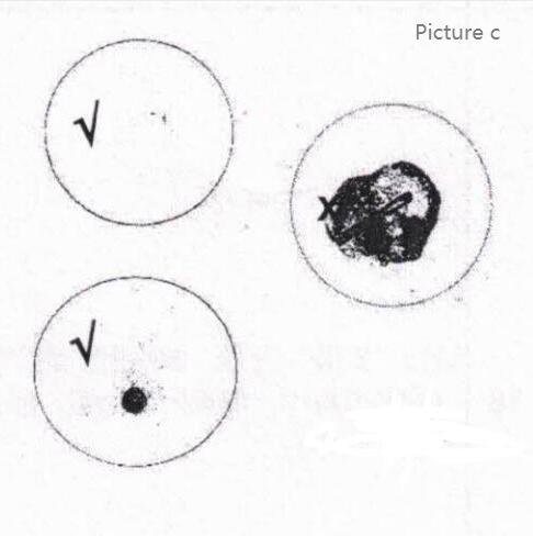
| 15 | Run the Setup wizard and follow the guidelines for the step-by-step installation steps.(During installation, if the problem occurs, resolve the Installation wizard again) | Go to Tools> Install, and complete the following setup steps: 1. Set the language and time and date 2. Valve test. Open the ink system hatch to make sure each solenoid moves to hear a “click” sound 3. Load the ink, remove the solvent box, and insert the ink into the solvent box slot. Perform ink irrigation. 4, and the loading of the solvent. Ininsert into the solvent slot to perform solvent irrigation 5. Fill with ink / solvent line (throat cleaning / system cleaning and emptying). Before performing this step, open the nozzle cover and place a waste basin under the nozzle. The machine automatically pumps the throat and cleans the system 6. Clean the spray nozzle. Ensure that the nozzle is clean and dry 7, inkjet inspection (the whole process is about 10 minutes). Check the stability of the ink line; the position of the ink line in the recovery tank is shown in Figure B; the switch effect is shown in Figure C. Close the headcover 8, printing quality test 9. Enter the inkjet machine information and service information After installation, check the level of the mixing cylinder, solvent cylinder, cartridges and solvent box. | |
| 16 | Install the nozzle at the specified production line | ||
| 17 | Edit customer operations and set the printing line parameters. | Create a new line setting, and you recommend the default setting | |
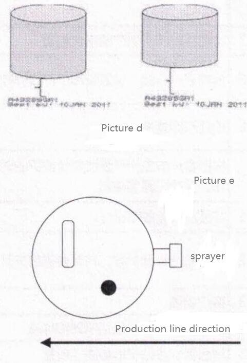
| 18 | Set the printing height | Adjust the distance between the nozzle and the product until the height of the printing jet meets the customer’s requirements, as shown in Figure D | |
| 19 | Online observation of the fault-free operation | Online production for more than 0.5 hours or continuous printing for 5000 times without failure | |
| 20 | Execute the backup system parameters, and save the backup file | Insert U disk, Tools> File Manager> Inprinter Backup, select U disk backup. Save the backed up Udisk data to your computer. | |
| 21 | Customer training | According to the “Customer Training” outline in the training manual | |
| 22 | Clean the workplace, including the machines and the environment | ||
| 23 | Place the service label in the chassis fixed position | ||
| 24 | Fill in the work order, training report, and installation certificate | ||
| 25 | Customer communication, sign on to confirm the acceptance |
Important pictures: