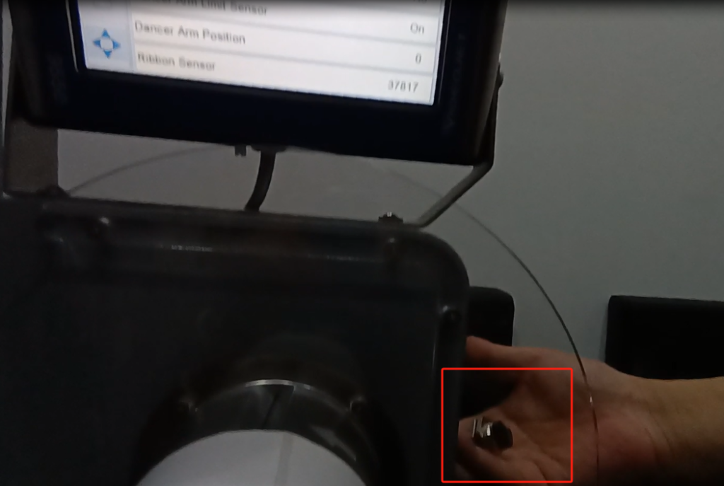
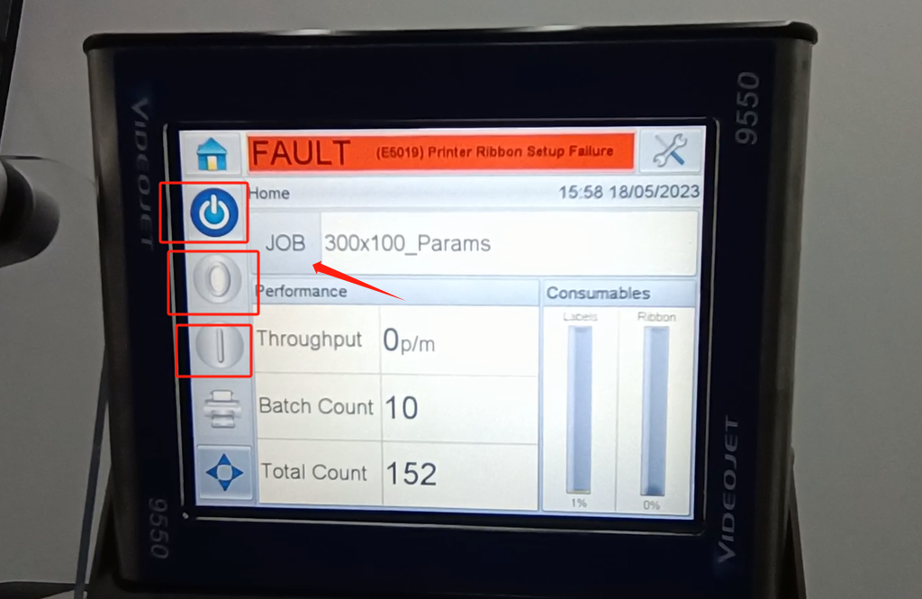
Let’s take a look at the vidit 9550 sticker machine on its menu. Let’s take a look at this main page. This side can see the fault bar. You can see a main menu with this button, and a run button switch. Then run then offline button these three. You can see a message from here.
Click on the information name to see his information. This is the information content.
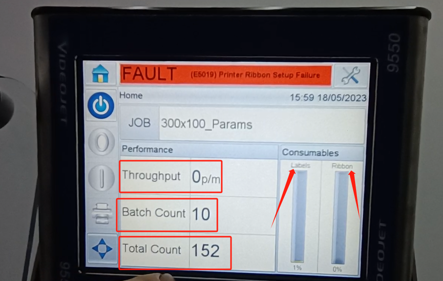
We are going back to it. And then with one print frequency here, just how many times do you print it per minute. Then you can see the print count here. There is a total count over here. Then we can see a consumables here. That’s how much the label is used. Then you can see a usage of the ribbon here. If you use the ribbon, he will show 0%.
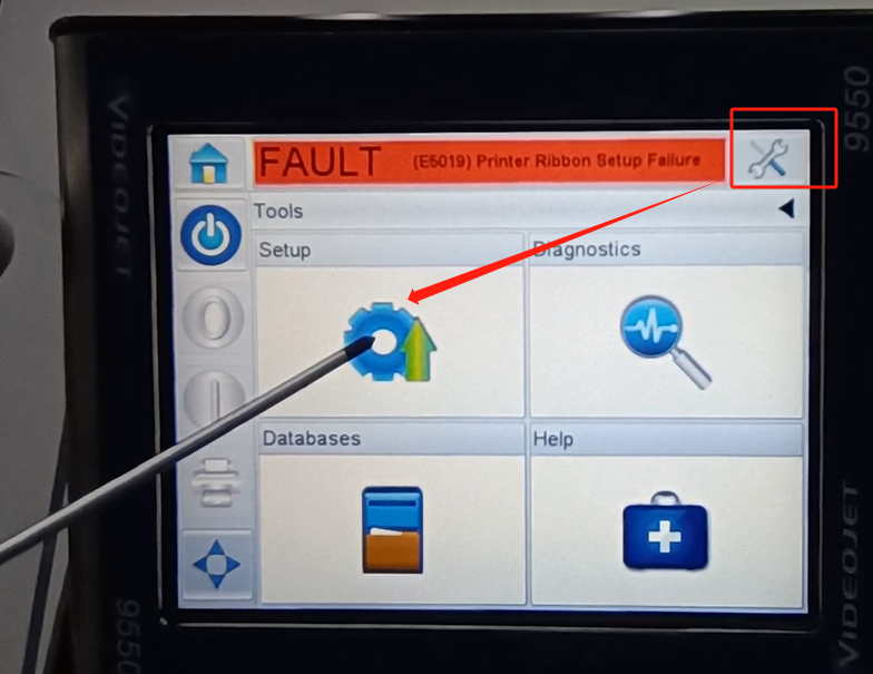
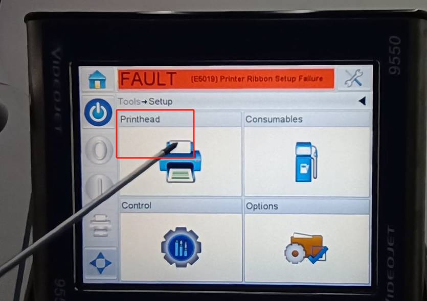
Then let’s look at the setup key. There is a nozzle to set up here first. This is the tool inside. Then the first one is the setting.
The first one inside is the nozzle.
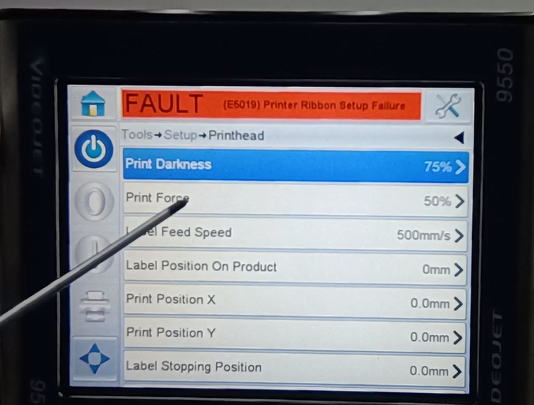
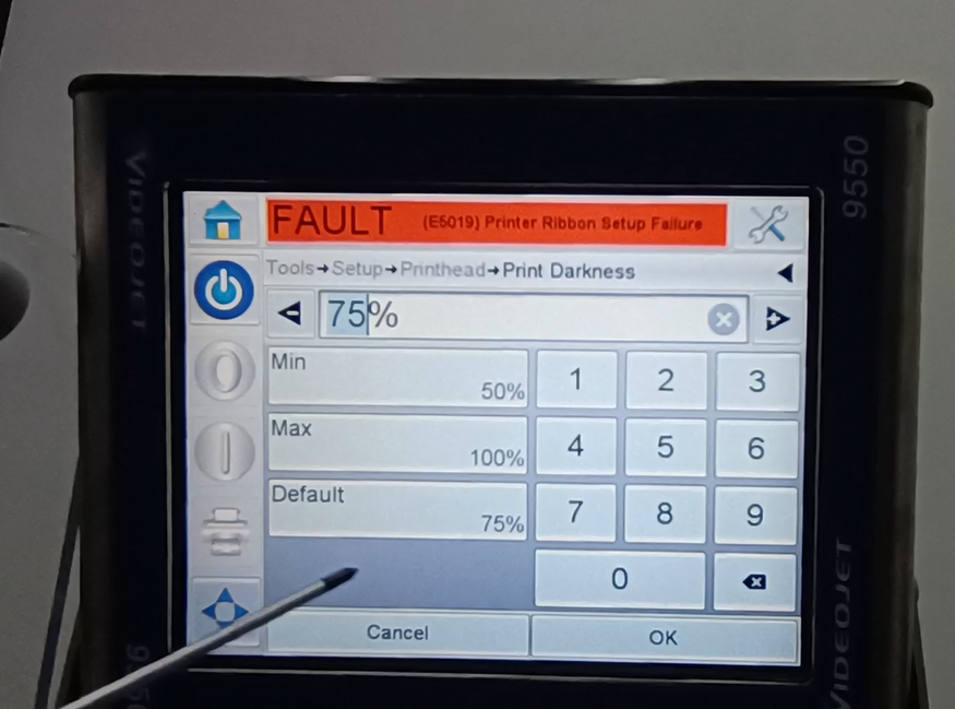
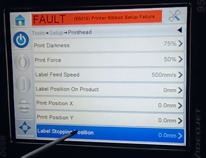
We can see the nozzle. The default blackness of a nozzle print is 75%.
We can change it here. Max 100% minimum 50%. Affects a depth we print.
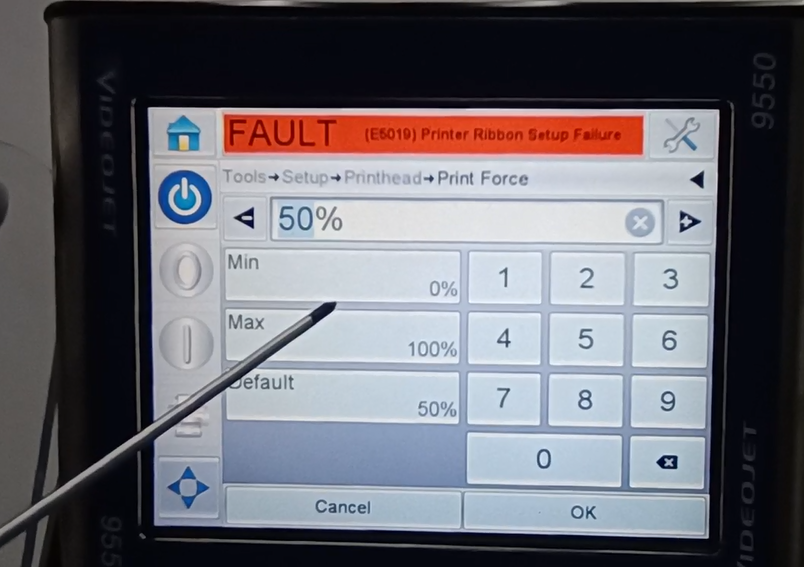
Then below is the spray printing force.
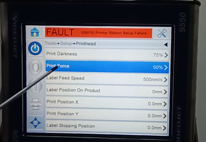
Here you can see the minimum is 0%, the maximum is 100%, and the default is 50%.
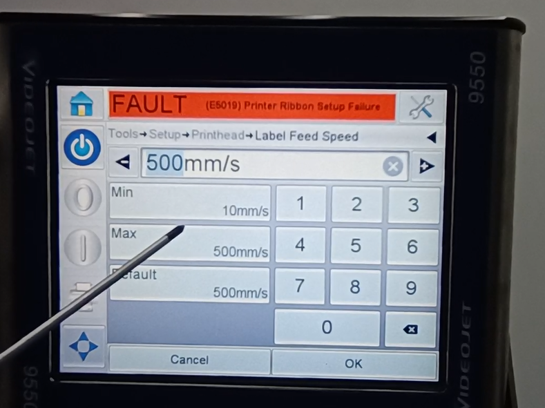
Then let’s look at the speed of the lab volume.
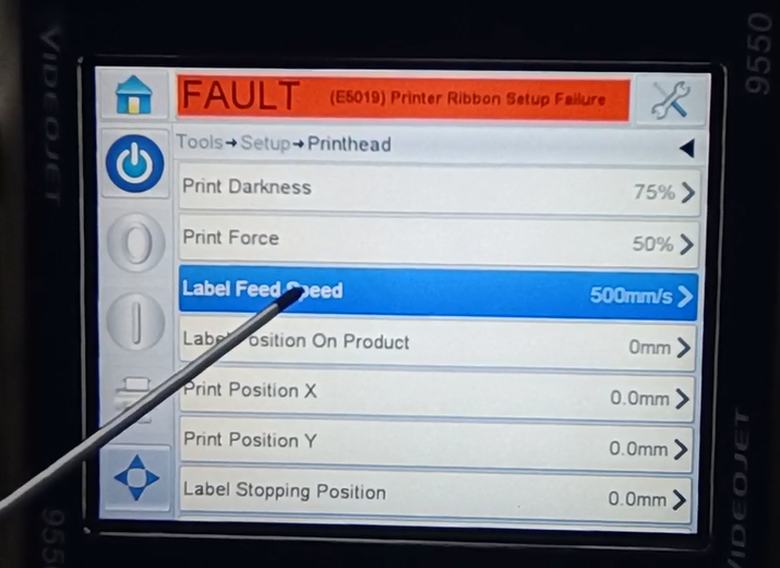
You can see it inside. The largest is 500, the smallest is the default, it is the fastest 500.
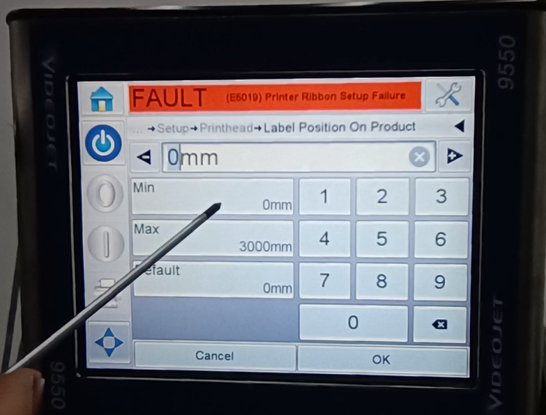
Then you can see a print delay here.
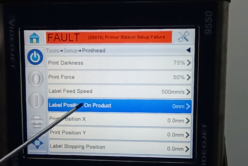
It can be modified here. The largest 3,000 and the smallest 0. We can modify it as needed.
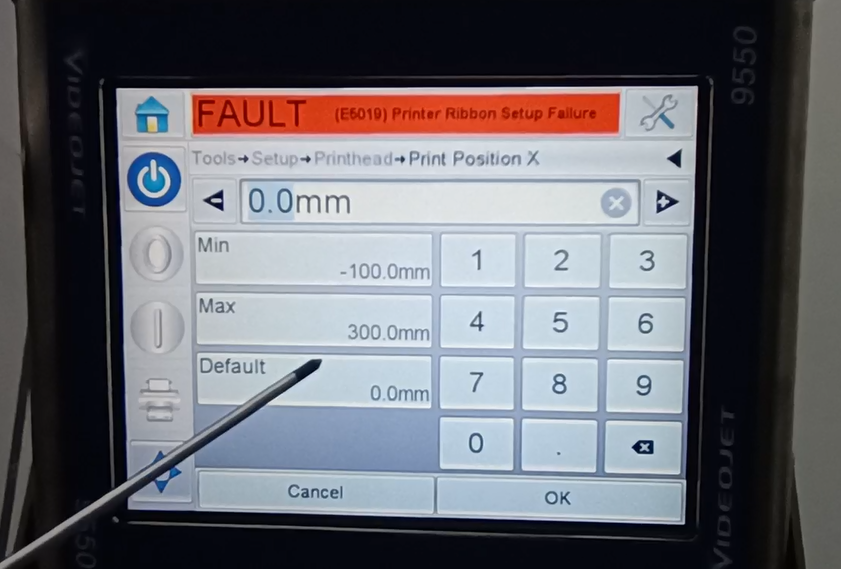
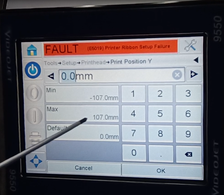
This shows the print location. Position x and the y position.
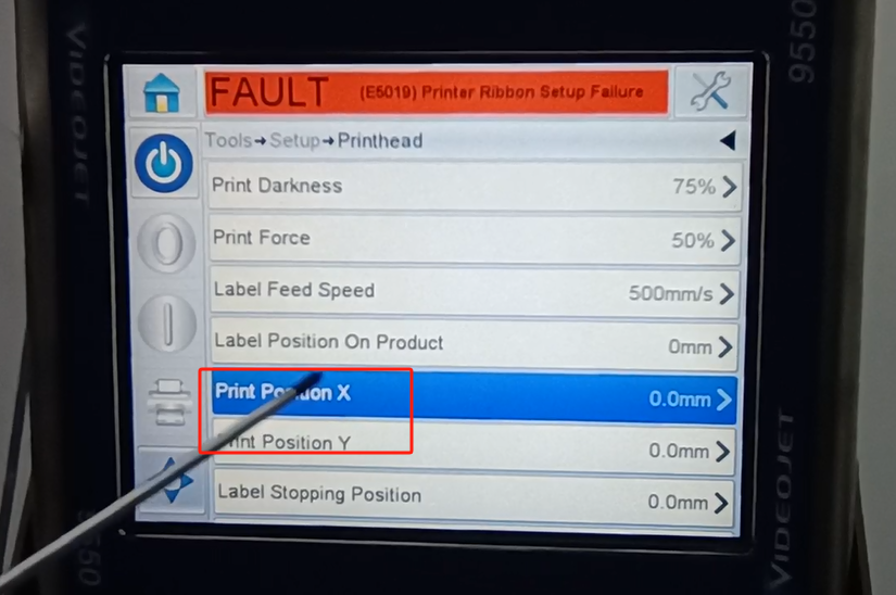
Then we can all make changes here. The maximum is 300, the minimum negative 100, the default is 0. We can modify it here. You can change it to 0 and so on.
The y position is the same. The smallest is a negative 107 and the largest is a positive 107.
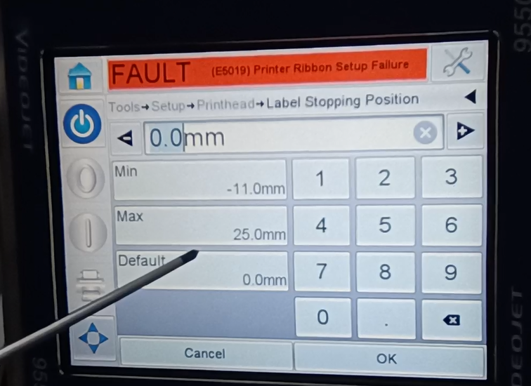
Then here is the label stop position.
-11 to 25 can be set within this range.
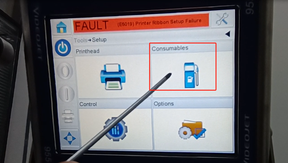
Let’s take a look at another consumable material.
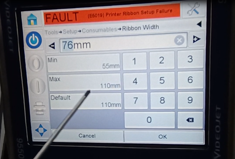
Inside, we can see a width of the consumables.
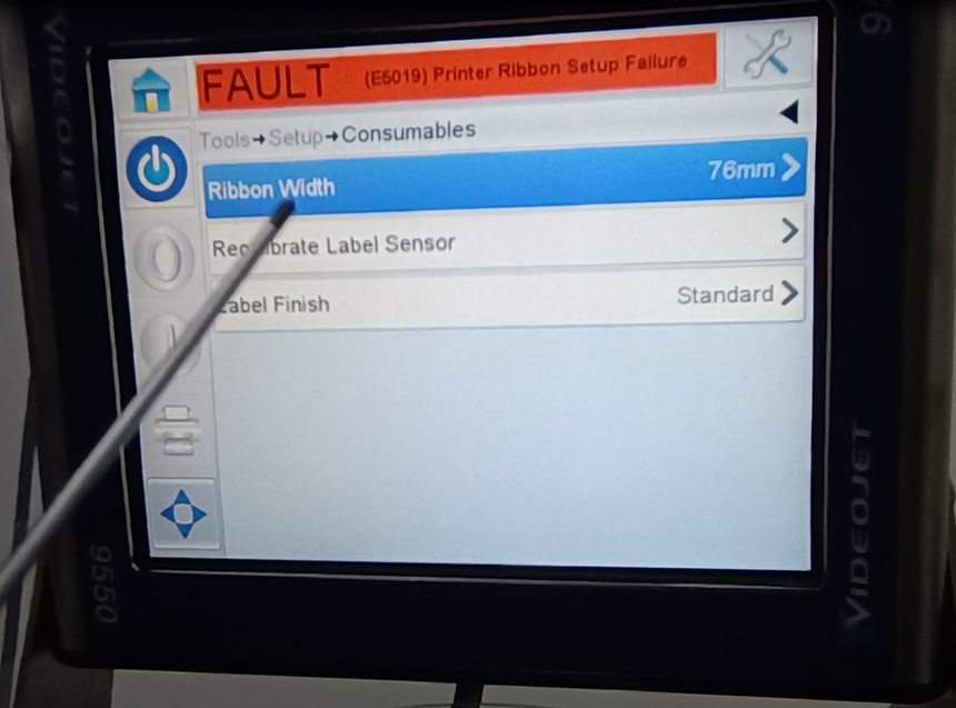
The maximum is 110, and the minimum is 55. This width is the explanatory ribbon. Need 55 mm width to 110.
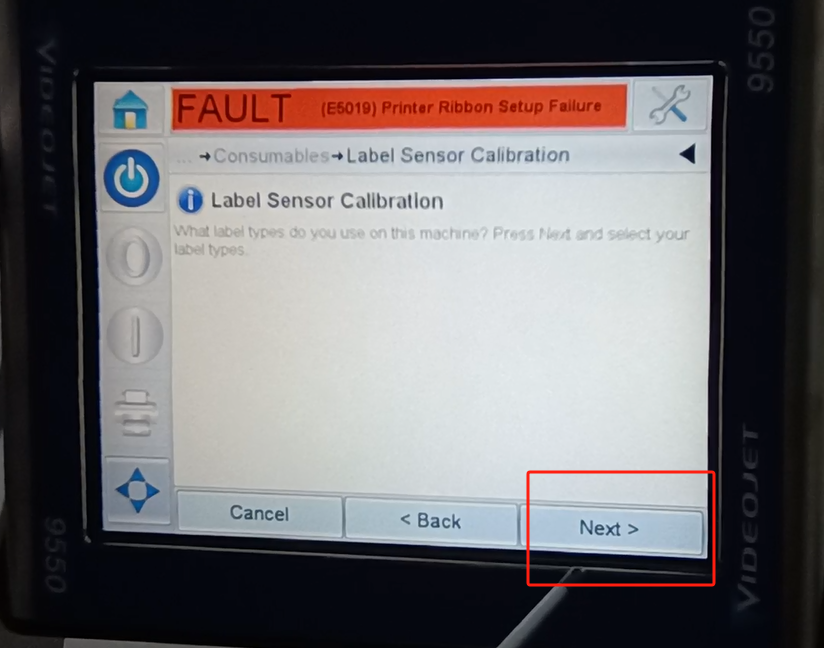
Then this second row is recalibrating the label sensor.
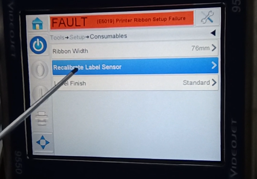
The next step is the calibration.
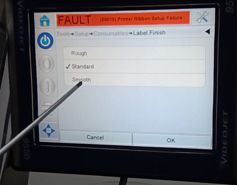
The following one is the label is complete.
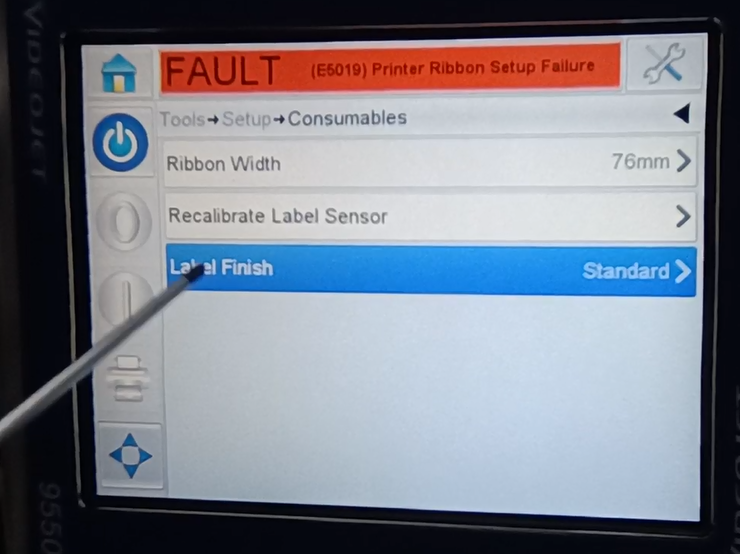
There are rough, have standard and smooth. Our general selection criteria.
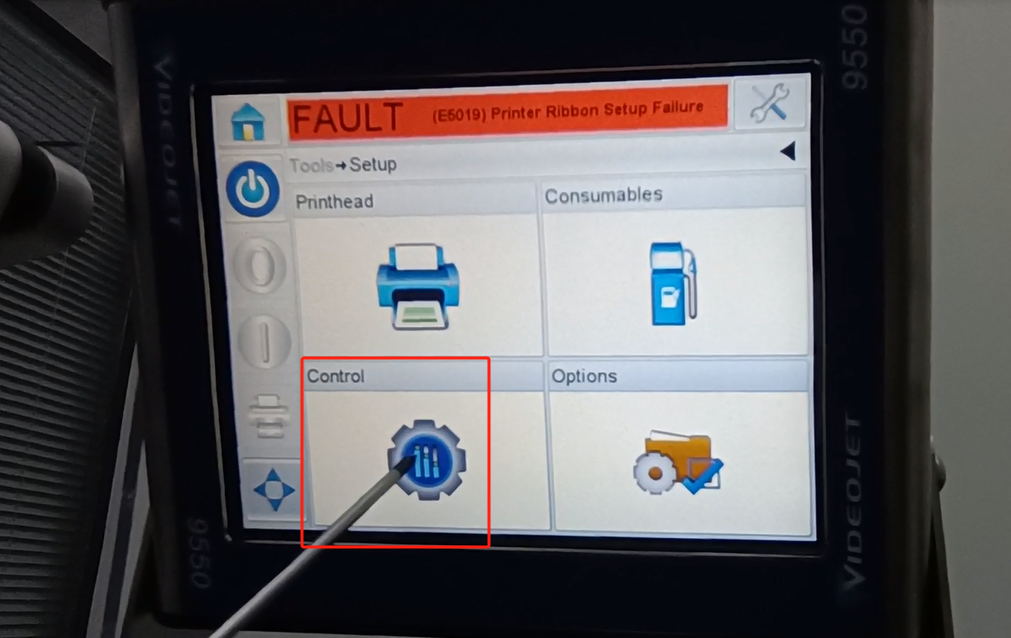
This is the setting-up. This is the consumables, and here is the control.
The first one inside is the clarity parameter. Mainly is a regulation of the parameters. You can create new ones right here. Then below is a installation. That’s the main language. This language has been spoken in so many languages before. Changes are also changed here. Then below is the installation wizard. We can install the wizard here and press one step. The first step is to set up the language. The next step may be corporate time. Follow its instructions, step by step. The installation wizard can be set up here. The next one is the calibration screen. We can calibrate the screen here. When the position of our buttons feels inaccurate, we can calibrate it. It lasts for 30 seconds and waits for 30 seconds.
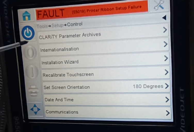
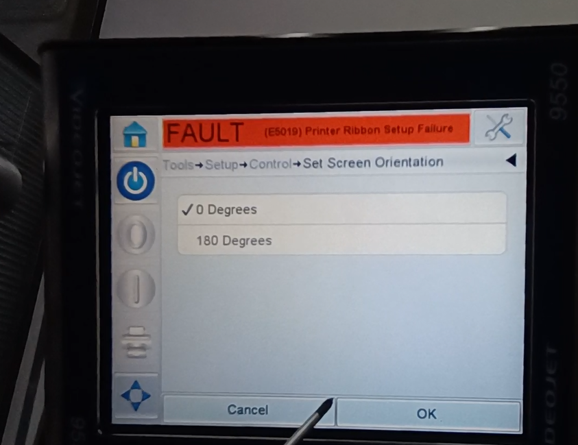
Below is the direction of a screen. With 0-180 degrees, 0 means the page. Let’s take a look at it.And it just goes the other way around. Then check it again at 180. and press OK.
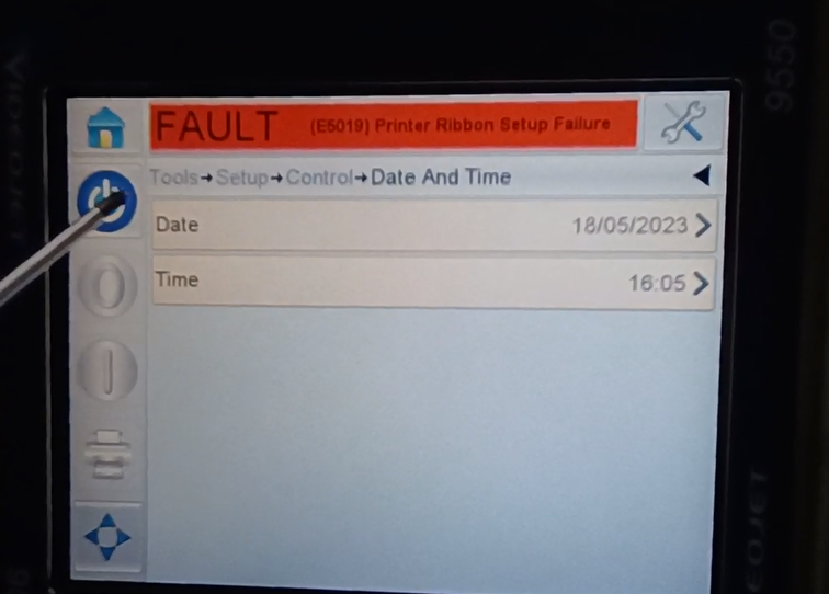
You can set the date and the time below. You can set both the date and the time all right here. It’s not being set up this time.
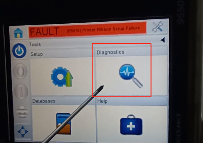
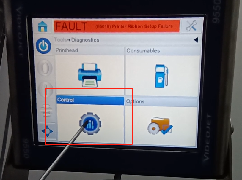
This is the control inside. There is no option in this one. We go back to the tool. Then we take a look at the diagnosis here.
This side is also a diagnosis.
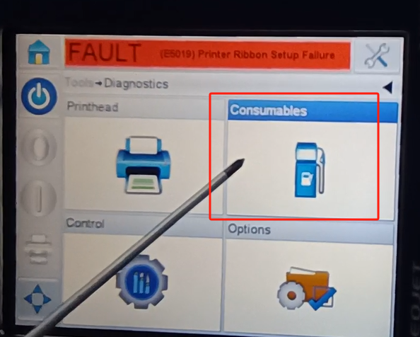
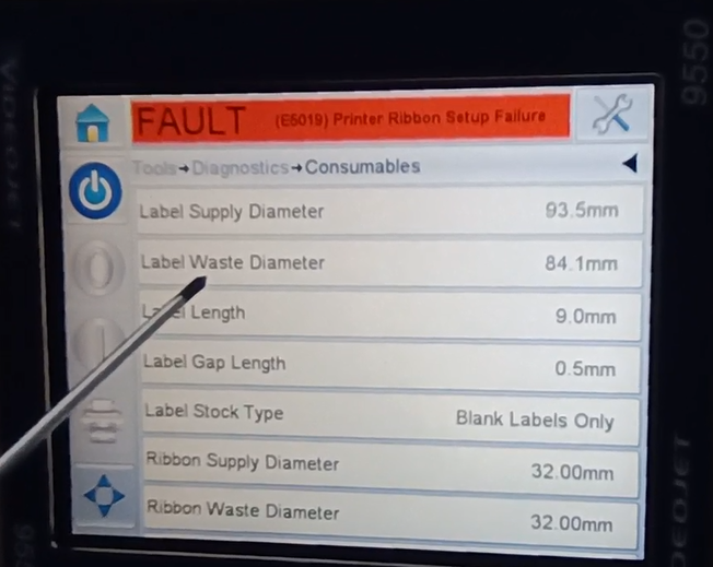
Inside of this diagnosis. What’s a diameter of our lab. One is the removed one.And a width. Depth means how much of it is apart. Is the interval between two labels can be set. This side is the ribbon. Its width can be set on this side.
The consumables that piece. Then we look at the controls.
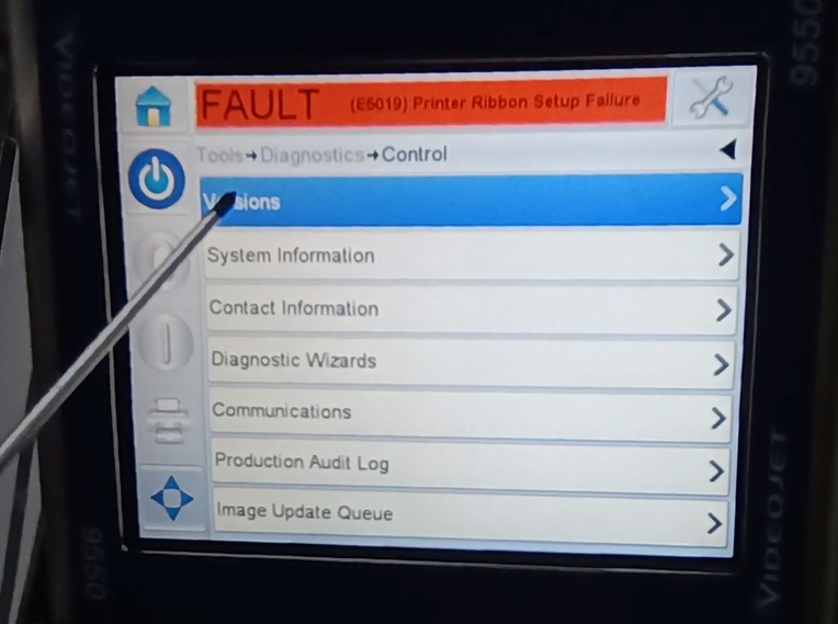
Inside is a version number, software version, system, and so on.
Let’s look at the print.
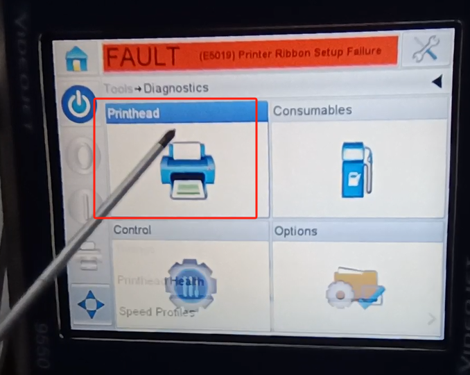
There is an input and output on the print side. If input, we click here.
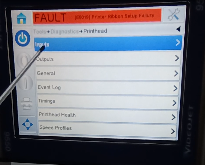
There are encoders on here.
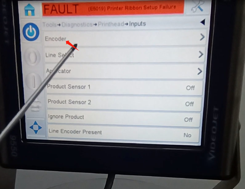
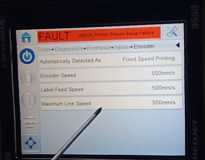
The speed can be set here. And this one is detected automatically. Is a fixed speed. Because it did not detect the encoder that we used. So I say he has a fixed speed. The same goes for the output.
And then let’s look at this, power 1 power 2. This is off, this OFF is off.This is a signal that it does not detect for power sources 1 and 2.
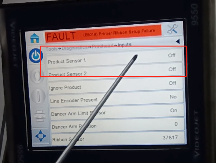
We can trigger the power supply 1 signal. The first signal is on and off. Give it a signal off, on, off, on this is power 1. Let’s test power supply 2 again, and we’ll plug it in to power supply 2. It can turn on and off this shows that our signal is good, and then the photoelectric is good. This is mainly about the menu explanation of this machine. We can’t use anything else, so we won’t talk.