
Engineering Blueprint: Anatomical Overview of Industrial Continuous Inkjet (CIJ) Printer Structure
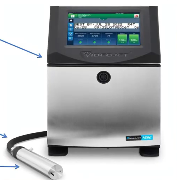
Maximizing equipment availability and executing rapid maintenance on a fast-paced production line requires an in-depth understanding of your machinery’s physical architecture. While a Continuous Inkjet (CIJ) printer behaves like a unified variable-data marking system from the exterior, its interior is sharply divided into isolated mechanical, hydraulic, and electrostatic sub-systems.
This structural layout ensures that highly volatile, conductive fluids remain entirely separated from the low-voltage logic processing units and high-voltage deflection electronics. A standard industrial CIJ coder is split into three main modules: the Main Cabinet Enclosure, the Flexible Umbilical Conduit, and the Remote Printhead Assembly.
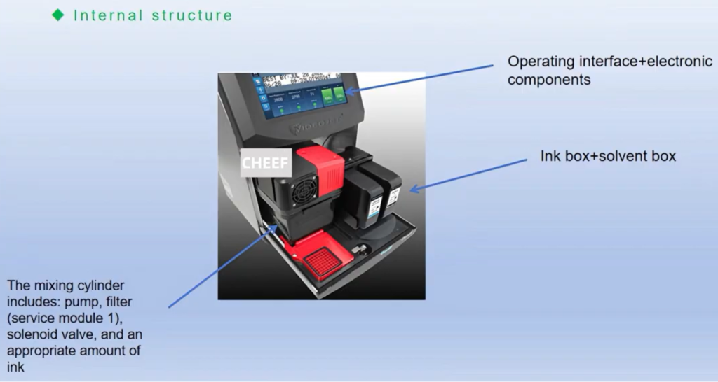
The Main Cabinet Enclosure: Core Processing and Hydraulics
Constructed from heavy-gauge, industrial-grade stainless steel (typically rated at IP55 or IP66 for moisture and dust protection), the cabinet is split internally by a structural firewall into two isolated sections: the Electronic Management Module and the Hydraulic/Fluid Loop Matrix.
The Electronic Management Module (Upper/Isolated Section)
- Central Processing Unit (CPU) & Logic Board: This core motherboard runs the machine’s operating system, calculates raster font matrices in real time, manages I/O signals from external conveyor sensors or shaft encoders, and modulates the drop-charging voltages.
- High-Voltage Electrostatic Supply (EHT Transformer): Converts incoming standard facility power into a stable, high-voltage DC output (typically $\approx 7,000\text{V}$). This output powers the deflection plates inside the remote printhead.
- Human-Machine Interface (HMI): A ruggedized, solvent-resistant touchscreen display that allows floor operators to choose printing templates, verify batch metrics, and run automated diagnostics.
The Hydraulic/Fluid Loop Matrix (Lower Section)
This dust-isolated area controls fluid storage, pressurization, and mixing:
- Ink and Make-Up Solvent Reservoirs: Receptacles that house specialized fluid cartridges. Modern systems utilize intelligent RFID or chip-validated connection ports to prevent chemical cross-contamination.
- The Main Hydraulic Pump: A high-precision, chemical-resistant gear or diaphragm pump that pressurizes the fluid line to propel ink toward the printhead.
- Viscosity Detection Array: An inline viscometer loop that monitors the ink’s fluid properties. If the solvent base evaporates, the system signals an internal solenoid valve to inject make-up fluid from the reservoir.
- Multi-Stage Filtration Block: A series of sequential micro-filters (including a main filter, pump protection filter, and head filter) designed to catch particulate contaminants before they can reach the tiny 40–70 micron nozzle orifice.
The Umbilical Conduit: Power and Fluid Transmission
Connecting the main cabinet to the remote printhead is a heavily reinforced, flexible sheath called the umbilical conduit. This conduit must protect several sensitive transmission lines from mechanical wear and chemical exposure:
- Pressurized Ink Supply Line: A chemical-resistant PTFE line that delivers pressurized ink to the printhead’s gun chamber.
- Vacuum Return Line: A vacuum line that draws unused ink back from the printhead recovery gutter to the main mixing tank.
- Solvent Flush Line: A dedicated fluid line used to inject pure solvent directly into the nozzle block during automated startup and shutdown sequences.
- Electrical Control Harness: A shielded cable bundle carrying sensitive piezo-oscillator signals, drop-charging voltages, high-voltage EHT lines, and printhead temperature sensor data.
The Printhead Assembly: Droplet Modulation and Deflection
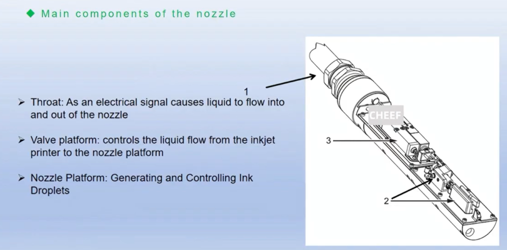
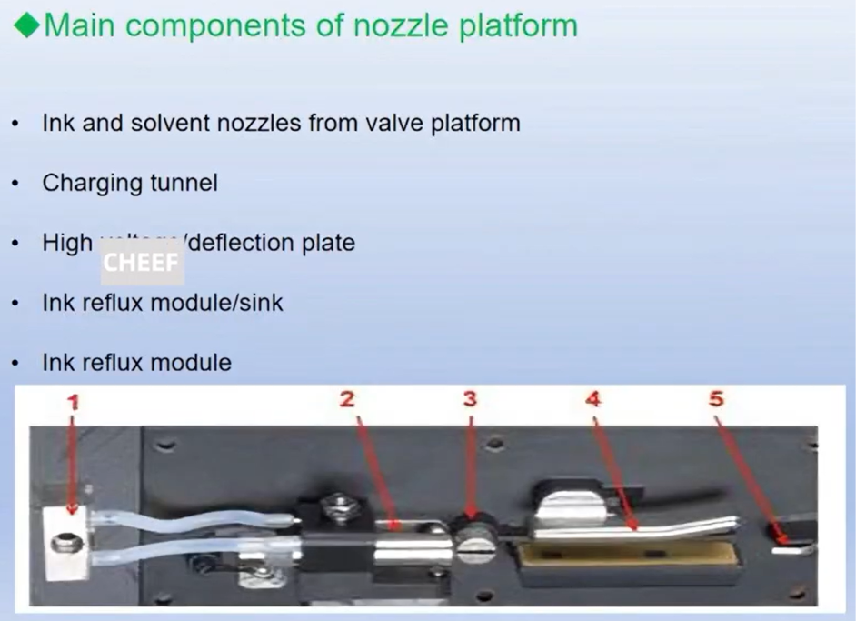
The remote printhead is where ink is broken down into independent droplets, charged, and precisely deflected onto passing products. Because it operates right at the production line, it is engineered for extreme precision.
Key Internal Components of the Printhead
- The Nozzle Block & Piezo Crystal: The pressurized ink enters a small chamber containing a piezoelectric crystal. The crystal vibrates at ultrasonic frequencies (e.g., 80 kHz), breaking the fluid stream into thousands of uniform drops as it exits the microscopic nozzle orifice.
- The Charge Electrode Tunnel: Located directly beneath the break-off point where the ink stream fractures into independent drops. This narrow slot applies a precise, variable voltage to individual droplets based on the data to be printed.
- The Phase Detection Sensor: An optical or electrical induction sensor that monitors the precise timing and structural quality of the drop break-off sequence. This feedback loop allows the CPU to continuously adjust the piezo vibration profile.
- High-Voltage Deflection Plates: Two parallel, thick metal plates charged to around $7,000\text{V}$. They create a powerful electrostatic field that bends the path of charged droplets, moving them vertically to form characters on the passing product.
- The Gutter (Return Pipe): A small intake tube positioned at the bottom of the printhead. It collects all uncharged, undeflected droplets and channels them back into the cabinet’s vacuum return loop, eliminating fluid waste.
Component Function and Preventive Maintenance Blueprint
| Structural Module | Primary Component | Preventative Maintenance Target | Operational Failure Mode |
| Main Cabinet | Multi-Stage Filtration Block | Replace every 2,000–4,000 hours based on fluid type. | Restricted fluid pressure; poor droplet break-off. |
| Main Cabinet | Viscosity Sensor Loop | Monthly verification with a manual fallback viscometer cup. | Incorrect ink-to-solvent ratios; character bleeding. |
| Printhead Assembly | Nozzle Orifice (40-70 $\mu$m) | Daily automated solvent flush; ultrasonic cleaning if clogged. | Crooked ink stream; complete loss of print output. |
| Printhead Assembly | Deflection Electrode Plates | Daily inspection; remove ink mist using specialized solvent. | High-voltage arcing faults; intermittent line stops. |
| Printhead Assembly | Recovery Gutter Tube | Verify physical alignment relative to the nozzle stream weekly. | Ink flooding inside the printhead housing. |
Standard Troubleshooting and Structural Failure Modes
- Symptom: Ink Flooding Inside the Printhead Housing
- Structural Root Cause: The recovery gutter is misaligned, or the return vacuum loop has lost suction due to a kinked line or saturated internal filter.
- Correction Procedure: Stop the ink stream. Clean the printhead housing thoroughly with premium solvent and dry it completely. Check the flexible umbilical for kinks, and verify the vacuum suction level via the cabinet’s diagnostic screen.
- Symptom: High-Voltage EHT Trip immediately on Start-Up
- Structural Root Cause: Residual ink or solvent moisture has built up across the physical air gap separating the deflection plates, causing an electrical short.
- Correction Procedure: Power down the EHT circuit. Spray the deflection plates with pure wash solvent to dissolve any ink residue, then blow the assembly completely dry using clean, compressed air.
- Symptom: Fragmented or Weak Print Resolution
- Structural Root Cause: The micro-filters in the fluid cabinet are beginning to clog, causing pressure variations that disrupt the droplet break-off frequency.
- Correction Procedure: Check the pressure drop across the internal filtration blocks. Replace the main ink filter assembly if it has exceeded its rated service hours.
Frequently Asked Questions (FAQ)
1. Why is the hydraulic system separated from the electronic boards in the cabinet?
Solvent-based CIJ inks and make-up fluids are highly volatile and conductive. Separating them from the electronics protects the delicate digital logic boards and high-voltage transformers from corrosive fumes, accidental fluid leaks, and short circuits.
2. What role does the phase detection sensor play in the printhead?
The phase detection sensor acts as a real-time monitor for droplet formation. It ensures that the charge electrode applies voltage at the exact millisecond a drop breaks away from the main ink stream. If the timing drifts, the drops won’t hold the correct charge, resulting in distorted text.
3. How often should the internal micro-filters be replaced?
Filter life depends on your factory’s running hours and fluid choices, but standard industrial guidelines recommend replacing the filtration block every 2,000 to 4,000 operating hours. Neglecting filter changes can lead to pressure drops and increased nozzle clogging.
4. What happens if the flexible umbilical conduit is bent past its minimum bend radius?
Bending the umbilical too sharply can pinch the internal PTFE fluid tubes, restricting ink delivery pressure or cutting off the gutter return vacuum. It can also strain the shielded electronic cabling, leading to intermittent signal failures or high-voltage shorts.
Watch the Full Video Tutorial:
This article summarizes the key points from our original video. Watching the full tutorial provides a clearer understanding of the procedures, demonstrations, and practical maintenance tips.
▶ Watch the full video below.
📺 Subscribe to the Cheef YouTube Channel to receive future maintenance guides, troubleshooting tutorials, product demonstrations, and industry updates.
