
Technical Blueprint: Understanding the Working Principle of Continuous Inkjet (CIJ) Coders
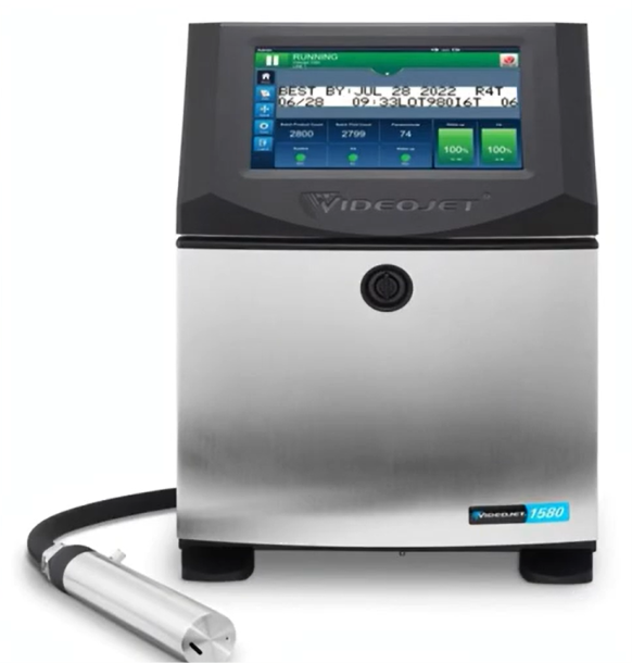
In fast-paced primary packaging lines—such as bottling plants, wire extrusion facilities, and high-speed pouch filling systems—contactless variable data marking is a critical baseline requirement. While Drop-on-Demand (DOD) or Thermal Inkjet (TIJ) systems rely on stop-and-go thermal expansion to eject ink intermittently, Continuous Inkjet (CIJ) systems function on an entirely uninterrupted fluid dynamic loop.
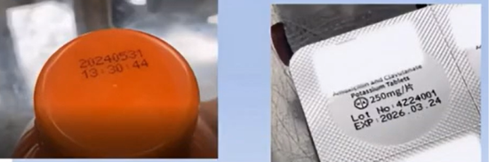
A CIJ coder propels a constant pressurized stream of ink toward a target substrate, using electrostatics to manipulate thousands of microscopic fluid droplets per second. This non-contact approach allows the system to print crisp lot codes, expiration dates, and 2D tracking matrices onto highly irregular, curved, or flexible surfaces at line speeds exceeding 300 meters per minute.
The Hydro-Electromagnetic Loop: Step-by-Step Mechanics
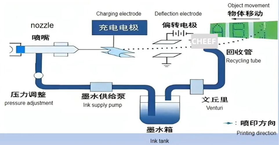
The CIJ system relies on precise synchronization between fluid dynamics, piezoelectric oscillation, and electrostatic control. The process follows a strict 5-stage mechanical sequence within the main unit and printhead:
[Main Tank / Pressurizing Pump]
│
▼
[Piezoelectric Nozzle] ───(Ultrasonic Fragmentation)───> [Individual Droplets]
│
▼
[Charge Electrode Tunnel]
│
(Variable Electrostatic Charge)
│
▼
[7,000V Deflection Plates]
/ \
(Charged Droplets) (Uncharged Droplets)
/ \
▼ ▼
[Target Substrate] [Recovery Gutter]
│
▼
[Recycle Circuit]
1. Fluid Pressurization and Hydraulic Delivery
The system mixes specialized, conductive solvent-based ink within a sealed main reservoir. A heavy-duty, internal hydraulic pump extracts this fluid, passes it through standard micro-filtration blocks to trap particulate contamination, and propels it down the umbilical conduit to the printhead at a tightly controlled, stable pressure.
2. Ultrasonic Droplet Fragmentation (The Piezo Oscillator)
Once inside the printhead assembly, the pressurized ink enters a localized gun chamber behind a microscopic nozzle orifice (typically ranging from 40 to 70 microns in diameter). A piezoelectric element (an acoustic oscillator) sits inside this chamber.
Driven by a high-frequency electric signal, the crystal expands and contracts at ultrasonic frequencies (often between 60 kHz and 120 kHz). This mechanical vibration ripples through the exiting ink column, breaking the continuous liquid stream into an identical, highly predictable sequence of independent, evenly spaced droplets.
3. Electrostatic Drop-Charging (The Logic Stage)
As the newly separated ink droplets pass through the narrow channel of the charge electrode, the system applies a variable command voltage. This voltage is modulated based on the specific shape of the character being generated:
- If a drop is needed to form part of a printed character, the electrode imparts a precise, negative electrostatic charge onto it.
- The exact voltage level varies; the specific amount of charge determines how far that drop will shift later in its flight path.
- If a drop is not required for the current character stroke, the charge electrode remains at $0\text{V}$, leaving the drop completely neutral.
4. 7,000V Deflection Field Manipulation
The stream of moving droplets then passes between two parallel deflection electrode plates. These plates are charged to a constant high voltage—typically around $7,000\text{V}$—creating a powerful, steady electrostatic field between them.
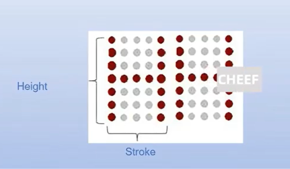
- When a negatively charged droplet enters this field, it experiences a proportional bending force that alters its flight path. Drops with higher charges are deflected further upward, creating the vertical (Y-axis) height of the printed character.
- The horizontal (X-axis) spacing of the text is generated naturally by the continuous perpendicular movement of the underlying product substrate on the production conveyor.
5. The Recovery Gutter and Recycling System
Droplets that remain uncharged pass straight through the $7,000\text{V}$ deflection field without altering their trajectory. They fly directly into a recovery intake pipe called the gutter.
A secondary vacuum pump draws these unused droplets out of the gutter, filters them, and returns them to the main ink tank. This continuous recycling loop minimizes fluid waste, which is why the process is called continuous inkjet printing.
Technical Parameter Baseline
| Component System | Functional Baseline | Engineering Significance |
| Nozzle Orifice Size | 40 $\mu$m to 70 $\mu$m standard diameter | Determines baseline droplet volume and character resolution details. |
| Piezo Modulation Frequency | 60 kHz to 120 kHz (acoustic) | Translates to 60,000–120,000 precise fluid drops generated per second. |
| Deflection Field Voltage | $\approx$ 7,000 Volts DC | Steady static field ensures highly accurate drop placement. |
| Print Head Distance Offset | 5 mm to 20 mm from substrate | Non-contact boundary allows safe coding over irregular shapes. |
| Viscosity Stabilization | Auto-monitored viscometer loop | Automatically injects makeup solvent to offset open-air evaporation. |
Dynamic Fluid Viscosity and Make-Up Fluid Management
Because CIJ systems expose ink to the open air at the recovery gutter, the volatile solvent base (typically Methyl Ethyl Ketone, Acetone, or Ethanol) evaporates continuously over time. This evaporation gradually increases the ink’s viscosity.
If ink viscosity drifts past its configured limits, it disrupts the droplet fragmentation process, causing irregular drop sizes and poor print quality.
To prevent this, industrial CIJ systems feature an integrated automatic viscometer loop:
- The control system continuously calculates the fluid’s viscosity by measuring its flow velocity through a calibrated internal sensor.
- If the fluid thickens, the machine automatically injects small, precise amounts of solvent make-up fluid from a secondary cartridge back into the main reservoir.
- This continuous adjustment maintains the precise fluid properties required for stable, crisp drop deflection.
Preventative Maintenance and Industrial Troubleshooting
While modern CIJ systems are designed for reliable 24/7 industrial use, the combination of quick-drying solvent inks and high-voltage electronics requires consistent preventative maintenance.
Critical Maintenance Protocol
- Daily Printhead Flushing: Use a dedicated cleaning solvent wash bottle to rinse out the nozzle orifice, charging tunnel, and deflection plates before shutting down the line for an extended period. This removes residual dried ink skin before it can clog the micro-nozzle.
- Deflection Plate De-Moisturization: Ensure the high-voltage deflection plates remain completely dry and free from ink mist. Moisture or ink buildup on these plates can cause electrical arcing, which instantly trips the safety circuit and faults out the machine.
- Gutter Alignment Verification: Inspect the printhead structure under magnification regularly to verify that the uncharged ink stream lands exactly in the center of the gutter intake. Mechanical vibrations on the production line can cause the nozzle alignment to shift over time.
Troubleshooting Technical Faults
- Symptom: High-Voltage EHT Fault (Electrical Arcing)
- Root Cause: Ink splatters or moisture buildup across the $7,000\text{V}$ deflection plates, creating a conductive path that short-circuits the electrodes.
- Correction: Shut down the machine’s high-voltage circuit. Wash the deflection plates thoroughly with clean wash solvent and dry them completely using oil-free, dry compressed air before restarting.
- Symptom: Character Distortion or Scrambled Codes
- Root Cause: Incorrect ink viscosity calibration, or a partial block in the nozzle that distorts the path of the ink stream as it enters the charging tunnel.
- Correction: Initiate an automated nozzle back-flush cycle to clear out particulate blockages. Run a manual viscosity test via the control interface to ensure the system isn’t over-concentrated due to a depleted make-up fluid cartridge.
- Symptom: Continuous System Clogging After Shutdown
- Root Cause: Failing to execute the standard solvent-flush sequence before powering down the unit, allowing ink to dry and solidify inside the 50-micron nozzle hole.
- Correction: Soak the nozzle assembly in an ultrasonic cleaning bath filled with premium printhead solvent for 15 minutes to dissolve the dried ink plug.
Frequently Asked Questions (FAQ)
1. Why does CIJ technology require a separate “make-up” fluid cartridge?
CIJ systems keep ink in continuous motion, and open-air exposure at the recovery gutter causes the volatile solvent base to evaporate over time. The make-up fluid cartridge provides pure solvent to automatically replace these losses, keeping the ink’s viscosity stable for clean drop fragmentation.
2. Can a CIJ printer mark onto non-porous materials like glass and glossy plastics?
Yes. Because CIJ coders utilize industrial solvent-based inks (such as MEK or acetone-based formulas), the printed marks dry almost instantly—often in under two seconds. This rapid drying allows the ink to adhere firmly to non-porous surfaces like aluminum cans, glass bottles, and extruded plastic conduits without smudging.
3. What is the operational difference between CIJ and Thermal Inkjet (TIJ) systems?
CIJ systems maintain a constant flow of pressurized ink and excel at high-speed, non-contact printing from distances up to 20 mm away, making them ideal for high-volume, irregular packaging. TIJ systems are “drop-on-demand”—they only eject ink when a product is present—and must be positioned much closer to the target (typically 1–2 mm), making them better suited for flat cartons or web lines.
4. How does a partial nozzle blockage impact the electrostatic charging sequence?
A partial blockage alters the velocity and straightness of the exiting ink column. If the stream enters the charge electrode tunnel off-center, the droplets won’t receive the correct electrostatic charge, leading to misplaced drops, distorted text, or ink missing the recovery gutter entirely.
Watch the Full Video Tutorial:
This article summarizes the key points from our original video. Watching the full tutorial provides a clearer understanding of the procedures, demonstrations, and practical maintenance tips.
▶ Watch the full video below.
📺 Subscribe to the Cheef YouTube Channel to receive future maintenance guides, troubleshooting tutorials, product demonstrations, and industry updates.
