
Dielectric Breakdown Analysis: Diagnosing and Remediation of High Voltage Faults on Videojet 1000 Series Printers
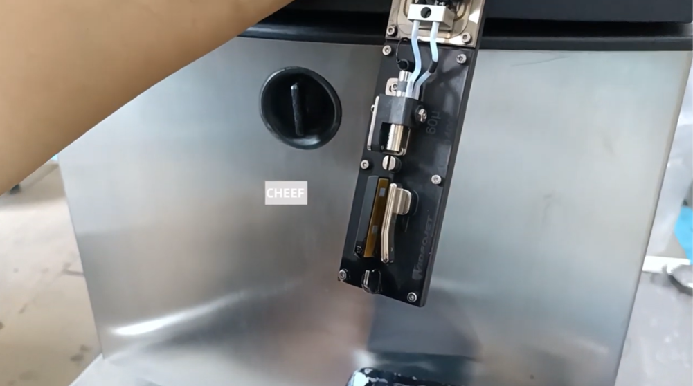
Continuous Inkjet (CIJ) printing relies on precise electrostatics. On production lines using Videojet 1000 Series systems (including the 1210, 1510, and 1610), the high-voltage (HV) deflection system is responsible for steering charged ink droplets onto the substrate to form legible characters. The printer generates an intense electrostatic field—often exceeding thousands of volts—between two opposing deflector plates.
When the printer detects an unexpected path of electrical resistance or a current leak within this field, it triggers an immediate high-voltage fault shutdown. This safety feature protects the internal control electronics, but it also halts production.
Understanding how to isolate these faults between printhead contaminants and internal hardware failure is essential for maintaining consistent line uptime.
Technical Insights: The Physics of Electrostatic Faulting
To diagnose high-voltage failures, it helps to understand how the printhead handles electrical charges. During operation, individual ink droplets pass through a charge tunnel where they receive a precise electrical charge. They then fly between a positive and a negative deflector plate. The electrostatic field bends the path of the charged droplets toward the product, while uncharged droplets fly straight into the recovery gutter.
Because the gap between these high-voltage plates is small, any breakdown in the clean, dry environment of the printhead deck will lower electrical resistance. The system tracks this resistance constantly. If current bridges the gap between the plates and the grounding rails, the motherboard cuts power to the high-voltage circuit instantly to prevent electrical arcing.
Phase 1: Printhead Diagnostic and Cleaning Sequence
The vast majority of high-voltage faults stem from physical buildup on the printhead deck rather than broken electronic components.
Step 1: Visual Inspection for Conductive Bridging
Stop the ink jet and disconnect the main power. Remove the printhead cover and inspect the deflector plates under a strong light. Look for ink buildup, encrusted pigment deposits, or microscopic airborne fibers spanning the gap between the plates. Even a single lint fiber soaked in conductive ink will create an electrical bridge that trips the system.
Step 2: Targeted Solvent Flushing
Position the printhead over a solvent recovery tray, angling it downward so fluid cannot track backward into the umbilical cord. Use a wash bottle filled with fresh, matching clean wash solvent to rinse the entire deflector array. Target the charge tunnel slot, the faces of both deflector plates, and the underlying insulator blocks to dissolve all residual ink film.
Step 3: Complete Forced Drying
This is a critical step in the process. Any residual wash solvent left behind on the plates or insulator blocks will mimic a short circuit and trip the high-voltage fault as soon as you restart the jet.
Use dry, low-pressure, filtered air to thoroughly blow out the spaces behind and beneath the deflector plates until all wet shine is completely gone.
Step 4: Assessing Nozzle Breakup Quality
Examine the nozzle faceplate for signs of structural stream splitting or poor drop formation. If the ink stream lacks coherence—forming a mist or spraying unevenly across the plates instead of breaking cleanly into distinct droplets—ink will rapidly accumulate on the deflector plates and cause the fault to return within minutes. If the stream is spraying or splitting, replace the print module or clean the nozzle orifice.
Phase 2: High Voltage Pack Hardware Diagnostics
If the printhead deck has been cleaned, dried completely, and verified to be free of debris, but the high-voltage fault code persists on the display screen, the failure is likely located inside the cabinet electronics.
Step 1: Locating the Power Module
Open the main printer cabinet door to access the lower electronics bay beneath the motherboard assembly. Locate the sealed block component designated as the High Voltage Pack.
Step 2: Inspecting Signal Integrity
Examine the primary high-tension wire leads and signal cords running from the high-voltage pack into the umbilical conduit. Look for insulation damage, micro-fractures in the conduit sleeve, or loose connections at the motherboard terminal plugs that could allow voltage to arc to the chassis frame.
Step 3: Module Replacement Protocol
The internal components of the high-voltage pack are sealed to prevent environmental contamination and cannot be repaired individually in the field. If the module fails to output the required voltage during software diagnostics, the entire block assembly must be unbolted and replaced as a single unit to restore reliable charging capabilities.
Technical Fault Remediation Matrix
| Active System Symptom | Probable Technical Root Cause | Field Action Plan |
| HV Fault Tripping Instantly on Jet Start | Residual wash solvent or dense ink bridge between the deflector plates. | Flush the printhead deck with fresh solvent, wipe clean surfaces with lint-free wipes, and use dry compressed air to dry behind the plates. |
| HV Fault Tripping After 5–10 Minutes | Crooked ink stream clipping the deflector plates and slowly building up a puddle. | Clean the nozzle plate face to remove micro-deposits, then use the manual alignment screw to center the stream into the gutter. |
| Persistent HV Fault with Dry Printhead | Internal insulation breakdown or component failure within the high-voltage pack. | Check wire leads for arcing; if internal circuits are damaged, replace the sealed high-voltage pack module. |
Preventative Practices for Clean Electrical Fields
- Eliminate Non-Technical Wipes: Never use standard paper towels or cotton swabs to clean the inside of the printhead. They drop microscopic fibers that stick to the high-voltage plates, absorb moisture, and cause recurring grounding faults. Use only approved lint-free technical wipes.
- Maintain the Positive Air System: Regularly inspect the printer’s positive-air pump and filter. This system maintains a steady outward airflow through the printhead cover, which prevents ambient dust, moisture, and plant debris from settling on the high-voltage components during production.
Frequently Asked Questions
Why does my printer show a high-voltage error immediately after I clean the printhead?
This almost always means the deflector plates are still damp with cleaning solvent. While the solvent clears away ink, the liquid itself is conductive enough to bridge the high-voltage gap and trip the system’s safety sensors. Use low-pressure air to dry the spaces behind the plates completely.
Can a high-voltage fault be caused by incorrect ink viscosity?
Yes. If the ink viscosity is too low, the drop generator cannot break the stream into clean, uniform droplets. This causes ink misting inside the printhead, and the airborne micro-droplets will settle on the deflector plates, causing a high-voltage short circuit over time.
Is it safe to measure the output of the high-voltage pack using a standard digital multimeter?
No. Standard shop multimeters are not rated to handle the high voltage levels generated by the pack, which can exceed several thousand volts. Attempting to test the live high-tension leads with a standard meter can destroy your tool and poses a serious electrical safety risk. Rely on the printer’s internal software diagnostic menu to check power output safely.
Watch the Full Video Tutorial:
This article summarizes the key points from our original video. Watching the full tutorial provides a clearer understanding of the procedures, demonstrations, and practical maintenance tips.
▶ Watch the full video below.
📺 Subscribe to the Cheef YouTube Channel to receive future maintenance guides, troubleshooting tutorials, product demonstrations, and industry updates.
