
Electronics Bay Cooling Fan Replacement for Videojet 1000 Series CIJ Printers
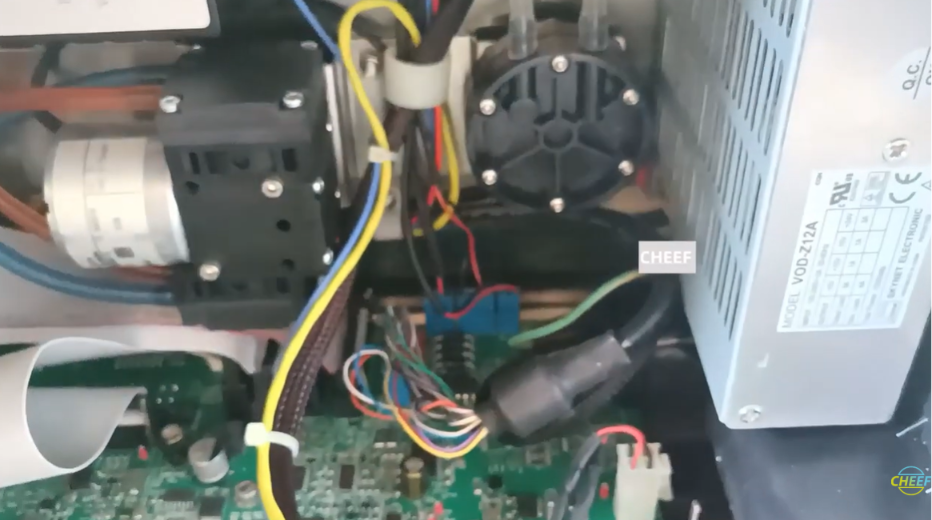
In the fast-paced environment of manufacturing, industrial continuous inkjet (CIJ) printers generate substantial internal heat. For the Videojet 1000 Series (including the 1210, 1220, 1510, 1520, and 1610 models), the internal cooling fan acts as the primary defense against thermal stress. It continuously circulates air across the power supply module, the main logic motherboard, and the ink core control circuit board.
Over time, constant exposure to plant dust, loose airborne fibers, and volatile solvent vapors can clog the fan blades or wear out its internal bearings. When a cooling fan fails, heat quickly builds up inside the sealed electronics enclosure. This triggers immediate safety shutdowns, intermittent hardware logic crashes, or component thermal damage.
Fortunately, replacing a worn or blocked cooling fan is an incredibly straightforward maintenance task that can be completed in minutes. This technical guide outlines the exact field-service steps required to safely disconnect, extract, and replace the electronics bay cooling fan.
Technical Indicators of Cooling Fan Failure
Maintenance personnel should check for these physical and software warning signs indicating that the cooling fan needs immediate attention:
- Loud Mechanical Noise: The fan produces a noticeable high-pitched buzzing, clicking, or rattling noise when the machine is booted up.
- Total Stoppage: The printer is powered on, but the fan blades remain completely still and no air can be felt exiting the cabinet vents.
- Core Temperature Overheating Faults: The user interface logs an active diagnostic fault code indicating that internal motherboard temperatures have exceeded safe operating boundaries.
Pre-Maintenance Safety and Electrical Isolation
DANGER: ELECTRIC SHOCK RISK
The internal electronics bay houses main AC voltage terminals. You must completely isolate the equipment from all power sources before proceeding with this repair.
- Shut Down the Print Stream: Turn off the ink jet using the control panel interface to ensure all automated fluid cleaning cycles finish safely.
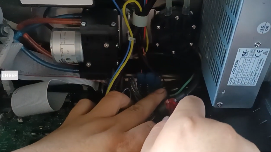
- Disconnect Main AC Power: Physically unplug the primary electrical line cable from the rear inlet socket of the printer.
- Use ESD Prevention: Wear an anti-static wrist strap connected directly to an unpainted metal section of the chassis to prevent static discharge from damaging nearby electronic components.
Step-by-Step Cooling Fan Replacement Procedure
The internal cooling fan is mounted directly inside the electronics compartment, located along the upper wall of the cabinet to pull heat out of the enclosure.
Step 1: Access the Internal Electronics Bay
Open the primary service cabinet door using the enclosure key to fully expose the internal motherboard, wiring harnesses, and power modules.
Step 2: Unplug the Fan Power Lead
Locate the dedicated power connection wire extending from the fan module down to the main logic board assembly.
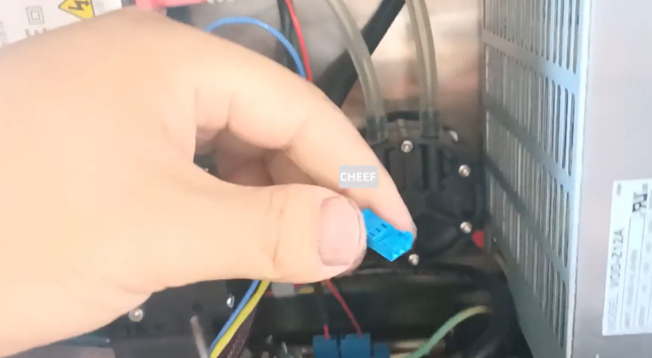
- Find the blue plastic inline terminal block plug.
- Firmly pull the blue wire terminal connector straight out of its socket to safely isolate the fan electrically.
Step 3: Remove the Fan Mounting Screws
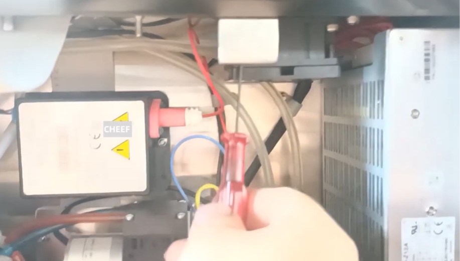
The cooling fan module is secured tightly to its upper mounting bracket by four individual retention screws—one located at each of the four corners of the square fan housing.
- Use a cross-recess screwdriver to loosen and back out the four mounting screws.
- Support the fan module with your hand while removing the final screws to ensure it does not drop into the open electronics bay below.
Step 4: Extract the Worn Fan Module
Carefully pull the old fan unit away from its bracket mount and lift it straight out of the electronics compartment.
Step 5: Install and Align the New Cooling Fan
Take the brand-new replacement fan module and check the airflow direction indicators stamped on the side of the housing.
- Position the new fan against the mounting bracket, ensuring it is oriented to correctly pull warm air out of the cabinet.
- Reinsert the four corner retention screws through the bracket and tighten them down evenly. Avoid overtightening to prevent cracking the plastic fan frame.
Step 6: Connect the Power Terminal
Take the blue plastic wire connector attached to the new fan module and plug it firmly back into its dedicated slot terminal on the lower circuit board. Ensure the connection clicks into place securely.
System Verification and Validation Testing
Once the cabinet door is securely closed and locked, run through this post-installation checklist:
- Restore Line Power: Reconnect the main AC power cord to the back of the machine.
- Initial Boot Check: Flip the main power switch to the ON position. Listen closely to ensure the new fan starts up instantly with a smooth, quiet hum.
- Airflow Inspection: Place a hand near the cabinet vent panels to confirm that steady air displacement is occurring.
- Verify Diagnostic Codes: Navigate into the software system menu and clear any historical overheating faults. Confirm that the status menu reads clear with zero active cooling system alarms.
Preventative Field Maintenance Reference Matrix
| Problem | Root Cause | Preventive Field Action |
| The new fan is running, but the printer still logs high-temperature warnings. | The main cabinet air filter is heavily clogged with dust and ink mist, blocking airflow. | Remove, clean, or completely replace the external cabinet air sponge filter elements. |
| The new fan does not spin at all after restoring power. | The blue plastic connector plug is loose, or it was inserted into the wrong terminal block. | Disconnect power, check the internal wire path, and make sure the blue terminal plug is pushed completely into its correct slot. |
| Rapid dust accumulation on the internal fan blades. | Operating the machine in a highly dusty or unventilated manufacturing area with the cabinet door left unlatched. | Always keep the service door closed tightly during production runs and establish a bi-weekly filter cleaning cycle. |
Frequently Asked Questions
Q1: Can I manually clean a noisy fan with washdown solvent instead of replacing it?
Using harsh industrial solvents like MEK or Acetone directly on the fan can melt the plastic fan blades and dissolve the factory grease packed inside the internal bearings. If a fan has become noisy due to bearing wear, it has reached the end of its operational lifecycle and must be fully replaced.
Q2: Does it matter which way the fan face points during installation?
Yes. Axial cooling fans are designed to move air in a single direction. Installing the fan backward will force hot ambient air back down onto the power supply and logic boards instead of venting it out, which can cause rapid overheating. Always verify the airflow arrow on the frame matches the original exhaust direction.
Q3: Are the cooling fans identical across all Videojet 1000 Series machines?
Most standard models (like the 1220, 1510, and 1520) use the same standard DC voltage cooling fan profile. However, specialized high-speed or dual-matrix units like the 1610 DH may utilize high-output fans or unique dual-fan layouts. Always cross-reference the voltage and part number listed on the old fan label to ensure perfect electrical compatibility.
Watch the Full Video Tutorial:
This article summarizes the key points from our original video. Watching the full tutorial provides a clearer understanding of the procedures, demonstrations, and practical maintenance tips.
▶ Watch the full video below.
📺 Subscribe to the Cheef YouTube Channel to receive future maintenance guides, troubleshooting tutorials, product demonstrations, and industry updates.
