
High-Voltage (HV) Pack Block Replacement for Videojet 1000 Series CIJ Printers
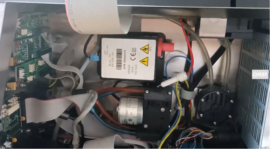
Continuous inkjet (CIJ) printing relies entirely on precise electrostatic manipulation. For the Videojet 1000 Series (encompassing heavy-duty production models like the 1210, 1220, 1510, 1520, 1610, and 1620), the High-Voltage Pack Block—also commonly referred to as the EHT (Extra High Tension) module—is responsible for creating the critical static deflection field. This high-potential field pulls and guides charged ink droplets down to micro-coordinates on your products.
Because this module continuously steps up energy to thousands of volts, the internal insulation or potting material inside the block can break down over years of exposure to manufacturing vibration, plant heat, and solvent vapor. When insulation breakdown occurs, the printer will drop the voltage field, throwing stubborn hardware alarms that shut down your entire packaging line.
Rather than purchasing an entirely new modular fluid core enclosure from the OEM, field maintenance technicians can complete a targeted HV block swap. This guide details the essential technical steps required to safely isolate, extract, and replace the High-Voltage Pack Block on Videojet 1000 Series machines.
Technical Indicators of HV Pack Block Failure
Before dismantling the internal core housing layers, evaluate these common symptoms that typically point to an absolute failure within the HV/EHT transformer circuit:
- Instantaneous “High Voltage Trip” Faults: The alarm logs a structural breakdown immediately upon attempting to open the ink jet, long before fluid can even touch the printhead deflector plates.
- Inability to Maintain Field Stability: Real-time telemetry shows the deflection potential diving dramatically during live operations, causing badly scattered or truncated print codes.
- Continuous “Lid/Hood Removed” Loops: A failed HV block can sometimes mimic an open safety loop by creating an electronic short circuit that tricks the main control board’s tracking logic.
Critical High-Voltage Isolation Protocols
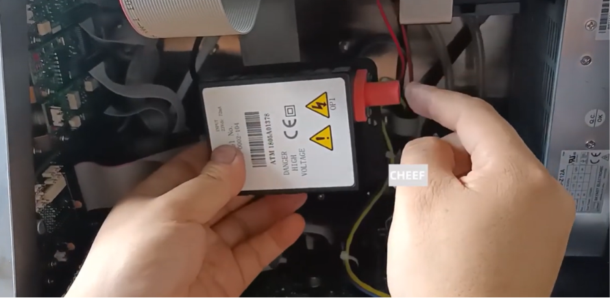
The HV block stores and transfers highly dangerous levels of static energy. You must follow these safety guidelines to prevent severe electrical shock or mainboard damage:
- Stop the Fluid Jet Sequence: Shut off the ink jet via the primary user interface to clear fluid lines and let any lingering hydraulic backpressure drop to zero.
- Sever Main Power Lines: Completely pull the main AC electrical power cord out from the back of the printer cabinet vault.
- Observe Mandatory Capacitance Cool-Down: Wait a minimum of 3 to 5 minutes before opening the cabinet doors. This allows large capacitors and internal transformer coils to naturally bleed off lingering electrical charges.
- Set Up Anti-Static Safety Gear: Wear an anti-static wrist strap clipped directly to the unpainted stainless steel cabinet chassis to ensure zero static transfer to nearby motherboards.
Step-by-Step High-Voltage Block Replacement
The High-Voltage Pack Block is positioned deep within the electrical tier of the main ink core block assembly, sitting directly underneath the primary circuit board layer.
Step 1: Open the Assembly Core Shell
Locate the four perimeter retention screws anchored to the outer plastic lid cover of the main ink core module. Remove the screws, pull the cover shield straight off, and place it aside safely.
Step 2: Disconnect the Primary Data Ribbon Bus
Gently unplug the wide, gray multi-pin ribbon communication cable from its header slot on the front face of the ink core board. Pull the connector housing straight out to avoid bending the rows of delicate metal pins.
Step 3: Unplug Associated Auxiliary Contacts
- Carefully disconnect any secondary multi-wire colored connector plugs (such as the blue terminal block interface) leading to the board.
- Unscrew and pull away the green/yellow wire that acts as the primary safety frame ground line.
Step 4: Displace the Main Core Board Layer
Remove the small mounting screws anchoring the circuit board to the core’s plastic internal frame. Lift the board assembly up with care and shift it safely over to the side of the workspace pocket.
Step 5: Unplug the Umbilical HV Feed Line
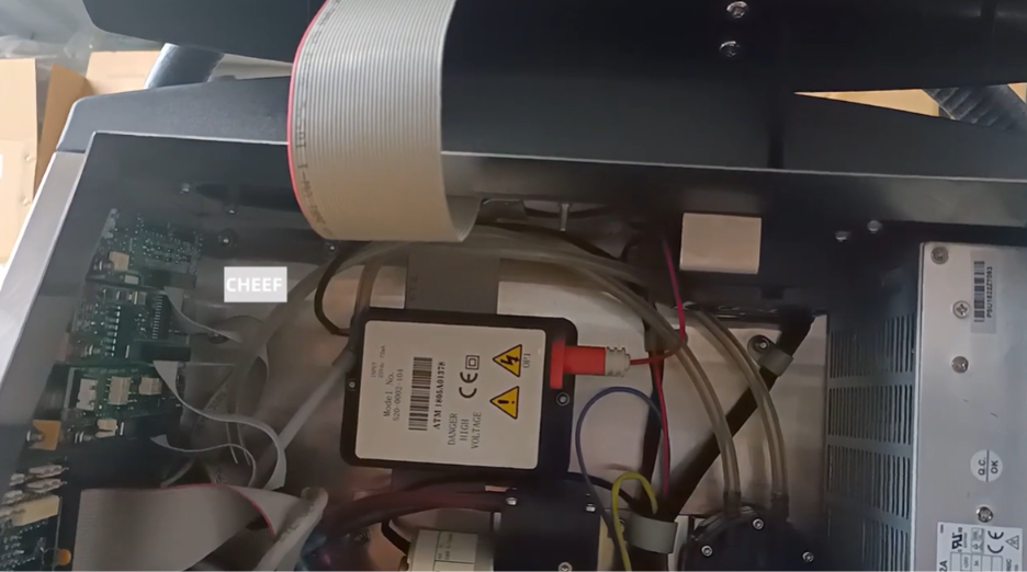
Locate the heavily insulated thick red wire coming directly out of the top or side of the potting module block. This line sends the static field down through the umbilical sleeve to the printhead. Carefully unscrew the lock nut or mounting screw securing the EHT/HV wire contact terminal and slide it loose.
Step 6: Extract the Damaged HV Block Module
Unfasten the primary retention screws holding the sealed potting block down into the plastic base plate of the core shell. Lift the failed module straight up and out of its mounting track.
Step 7: Mount and Wire the New HV Pack Block
- Take the replacement High-Voltage Pack Block module and slide it firmly into the empty housing channel, making sure the terminal leads line up perfectly with the original layout.
- Insert the mounting screws and tighten them down gently to anchor the module frame into the plastic core base.
- Reconnect the thick red umbilical HV line wire to the undercarriage or output terminal of the new block, ensuring the spring washer and retention screw are tightly fastened to prevent high-voltage arcing.
Phase 4: Module Reassembly and Commissioning
- Re-mount the Circuit Board Layer: Align the ink core board over the plastic standoffs and secure it back down using the original board screws.
- Reconnect Electronic Plugs: Push the colored auxiliary harness blocks back into their terminal pins. Securely fasten the green/yellow ground wire back to its grounding point.
- Secure the Data Ribbon Bus: Push the gray communication ribbon cable firmly into its slot header until the side retention clips click shut.
- Replace the Outer Shell Cover: Set the plastic core lid back over the top assembly and tighten down the 4 outer cover screws to protect the new electronics block from fluid vapors.

Post-Replacement Startup Check
Before running production packaging, execute this commissioning procedure to ensure the circuit is fully functional:
- Power Up and Check Alarms: Plug the main AC power cord back in and switch on the printer. Confirm that the main screen boots into an “Idle” status with zero high-voltage faults flashing.
- Initiate a Live Calibration Loop: Start up the jet stream loop. Enter the service diagnostic screen to monitor the real-time EHT field output. The voltage potential should match your factory parameters exactly.
- Conduct a Print Quality Run: Print a series of multi-line test codes onto cardboard or film. Check for clean character heights and razor-sharp drop alignment, which indicates that the deflection field is working perfectly.
Field Troubleshooting Reference Matrix
| Observed Symptom | Potential Root Cause | Corrective Field Action |
| The printer powers up fine, but trips instantly the moment the jet stream engages. | The red HV/EHT wire terminal screw is loose, or the spring washer was left off. | Turn off the machine, disconnect power, open the core block, and make sure the thick red wire is securely fastened to the base of the block with its spring washer. |
| The interface panel logs a continuous communication error code on boot up. | The main gray ribbon cable or auxiliary board connectors are loose. | Open the plastic lid cover and verify that the data ribbon cable is pressed completely into its header slot. |
| The print text looks squished or drops lines intermittently. | The high-voltage deflector plates inside the printhead are dirty or wet with solvent. | Thoroughly wash down the printhead components with fresh cleaning solvent and use clean compressed air to blow them 100 percent dry. |
Frequently Asked Questions
Q1: Is it possible to test if an HV block is broken using a standard digital multimeter?
Because the HV block steps up voltage to high levels during live operations, a standard digital multimeter cannot safely measure its live peak output directly without blowing the meter’s internal fuses. Instead, technicians test the block by checking its internal continuity ohms while the machine is powered off, or by checking for stable supply input power on the motherboard’s supply rail.
Q2: Can a single high-voltage block work across both a 60-micron and a 70-micron Videojet printer?
Yes, the underlying HV pack hardware module shares the same basic voltage conversion architecture across most standard 1000 Series models. The actual output strength of the deflection field is controlled dynamically by calibration settings stored in the main unit’s motherboard software, which automatically adjusts based on the nozzle size you select in the menu.
Q3: What happens if there is residual ink dust or grime underneath the new HV block during installation?
Any conductive ink dust, debris, or moisture left in the bottom of the plastic core mounting channel can create an unintended ground path. This will cause the high-voltage field to arc or short circuit against the chassis before it can travel down the umbilical line to the printhead. Always wipe the mounting track completely clean and dry before dropping the new module in.
Watch the Full Video Tutorial:
This article summarizes the key points from our original video. Watching the full tutorial provides a clearer understanding of the procedures, demonstrations, and practical maintenance tips.
▶ Watch the full video below.
📺 Subscribe to the Cheef YouTube Channel to receive future maintenance guides, troubleshooting tutorials, product demonstrations, and industry updates.
