
Power Supply Module Replacement for Videojet 1000 Series CIJ Printers
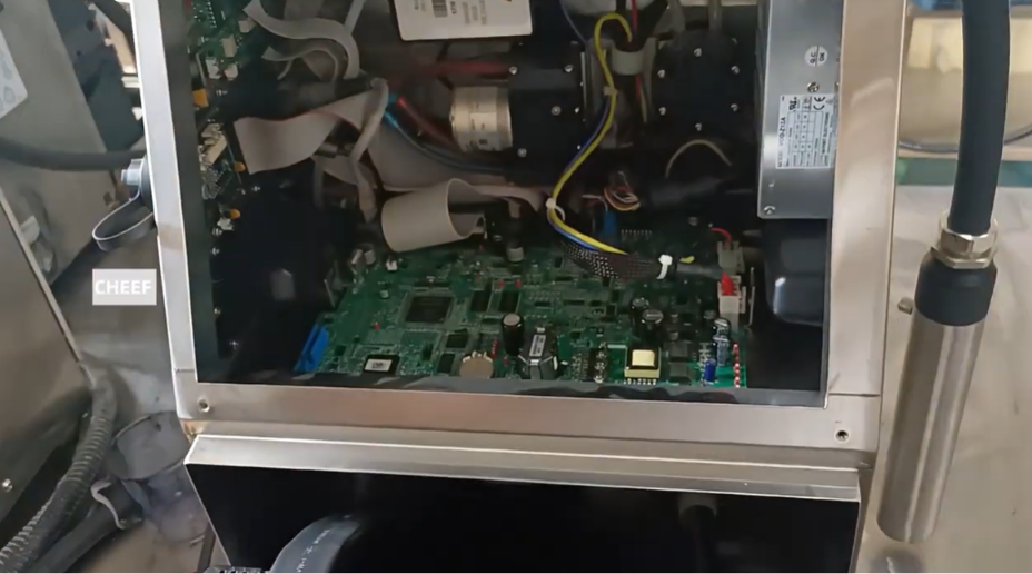
An industrial continuous inkjet (CIJ) printer relies entirely on clean, well-regulated electrical power to manage its internal systems. For the Videojet 1000 Series (including the 1210, 1220, 1510, 1520, and 1610 models), the Power Supply Module sits inside the electronics bay as a critical foundation. It converts standard AC line power into the precise DC voltages required by the primary motherboard, ink core board, pump motor, and the high-voltage deflector pack.
Over years of continuous plant operations, high ambient temperatures, line voltage surges, and airborne contaminants can degrade the internal capacitors or transformer circuits within the power module. When a power supply fails or weakens, it can cause unpredictable system crashes, low-voltage faults, or a total failure to boot.
Replacing a faulty power supply module is a standard electrical maintenance routine that quickly restores line stability. This manual outlines the professional field service steps required to safely isolate, extract, and replace the power module on Videojet 1000 Series printers.
Technical Indicators of Power Supply Failure
Before opening the electronics cabinet, technicians can evaluate these primary indicators pointing to power module breakdown:
- Total Power Failure: The main switch is turned on, but the control panel screen, cooling fans, and motherboard LEDs stay completely dead.
- Intermittent Resetting: The printer reboots on its own during high-load actions, such as initiating the pump drive or engaging the high-voltage pack.
- Low-Voltage Alarm Faults: The main user interface logs explicit software faults indicating that the 24V or 5V electrical rails have dropped below operational limits.
Mandatory High-Voltage Electrical Isolation
DANGER: RISK OF ELECTRICAL SHOCK
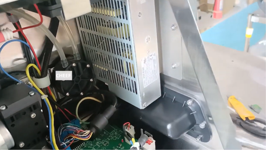
The power supply module connects directly to incoming mains electricity. You must fully isolate the machine from its power source before loosening any screws or panel covers.
- Turn Off the Jet Loop: Properly shut down the ink jet via the control interface to clear any standing fluid pressure.
- Disconnect Main AC Power: Physically pull the main power cord completely out of the printer cabinet inlet.
- Wait for Residual Discharge: Allow the unit to sit idle for at least 3 to 5 minutes to ensure that any large internal capacitors have completely discharged their stored electrical energy.
- Set Up Static Grounding: Wear an anti-static wrist strap hooked directly to the metal chassis of the printer to protect the main circuit boards from static damage.
Step-by-Step Power Supply Module Replacement
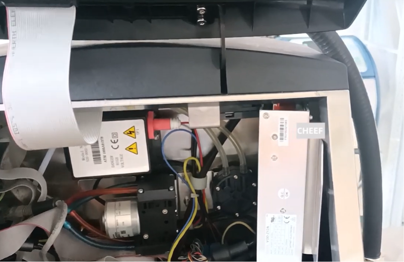
The power supply module is positioned inside the electronics compartment, generally situated behind or underneath the main control motherboard assembly.
Step 1: Access the Electronics Vault
Use the cabinet key to unlock the rear electronic service door of the printer enclosure. Swing the panel door wide open to expose the main motherboard, wiring harnesses, and electrical shielding plates.
Step 2: Document and Unplug Wiring Connections
The power supply module distributes electricity through several multi-pin wire harnesses connected directly to the motherboard.
- Carefully take a digital photograph of the terminal blocks and plugs to note the exact routing of the cables.
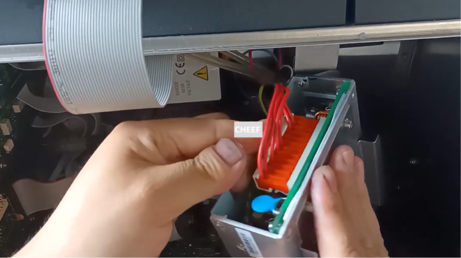
- Gently disconnect the AC input lines (Line, Neutral, and Ground) from the power module’s input terminal block.
- Unplug the multi-color DC output harnesses that send regulated power up to the primary logic boards.
Step 3: Remove the Faulty Module Mounting Screws
Locate the structural mounting screws anchoring the power module frame to the internal stainless steel electronics chassis. Using a cross-recess or hex screwdriver, remove the screws completely while holding the module steady so it does not drop against the floor of the cabinet.
Step 4: Extract the Power Module
Carefully lift the old power supply module out of its mounting pocket. Guide its attached wires past any adjacent components, making sure not to snag or pull on any neighboring motherboard connections.
Step 5: Mount the New Power Supply Module
Position the new replacement module directly over the chassis alignment pins. Reinsert the structural mounting screws and hand-tighten them firmly to ensure the module frame is securely grounded against the cabinet chassis.
Step 6: Reconnect Electrical Harnesses
Using your reference photo, plug all the wiring lines back into their exact terminal positions:
- Connect the DC output harnesses firmly back into their matching motherboard slots.
- Securely latch the incoming AC mains lines (Mains Input) into the dedicated terminal block, ensuring correct polarity (Line to Line, Neutral to Neutral, Ground to Ground).
System Calibration and Post-Replacement Validation
Once the wiring paths are checked and the electronics bay door is closed, follow this validation checklist:
- Initial Power Up: Plug the main AC power cord back into the printer wall outlet and flip the power switch on. Verify that the screen lights up normally and the cooling fans start spinning immediately without any unusual noises.
- Monitor System Diagnostics: Navigate to the service tools and check the electronic telemetry display. Confirm that the voltage readings for all electrical rails (typically +5V, +12V, +24V) are stable and well within standard OEM operational specs.
- Live Print Cycle Test: Run a test print job to verify that the high-voltage deflector pack and ink pump motor can draw power simultaneously without triggering any voltage dips or system reset loops.
Field Maintenance Reference Matrix
| Operational Issue | Root Cause | Corrective Service Action |
| New power module installed, but the printer stays completely dead. | AC input wires are loose, or the main cabinet fuse is blown. | Disconnect power, open the panel, and verify that the AC lines are tightly seated. Check and replace the main incoming line fuses if necessary. |
| The unit powers up, but logs an instantaneous EHT or High-Voltage Fault. | The high-voltage lines running from the motherboard to the printhead are dirty, or the power supply rail is uncalibrated. | Thoroughly wash down and dry the deflector plates in the printhead to clear any short circuits. Verify the 24V supply output under load. |
| Excessive humming or heat coming from the power supply bay. | The cabinet cooling fan or air filter is clogged with dust and ink mist. | Clean or replace the cabinet air filters to ensure proper ventilation across the power supply components. |
Frequently Asked Questions
Q1: Can I adjust the voltage trim potentiometer on a new Videojet power supply module manually?
Most certified replacement power supply modules come pre-set from the factory to match standard operating parameters. You should only adjust the internal voltage trim screw if an authorized technician verifies with a digital multimeter that a power rail is sagging under active mechanical load.
Q2: What happens if the input AC mains wires are accidentally reversed during reassembly?
Reversing the Line and Neutral lines can create a serious safety hazard and may cause unpredictable behavior by leaving circuits energized even when the power switch is off. Always double-check your wiring diagrams or reference photos before restoring power to ensure the connections are correct.
Q3: Why is it vital to replace the cabinet air filter whenever a power supply module fails?
Power supply units naturally generate a lot of heat while converting electricity. If the printer’s cabinet filters are packed with dust, fibers, or dried ink mist, heat builds up rapidly inside the enclosure. This thermal stress is one of the leading causes of premature power component failure.
Watch the Full Video Tutorial:
This article summarizes the key points from our original video. Watching the full tutorial provides a clearer understanding of the procedures, demonstrations, and practical maintenance tips.
▶ Watch the full video below.
📺 Subscribe to the Cheef YouTube Channel to receive future maintenance guides, troubleshooting tutorials, product demonstrations, and industry updates.
