
Replacing the Pressure Pump on Videojet 1000 Series CIJ Printers
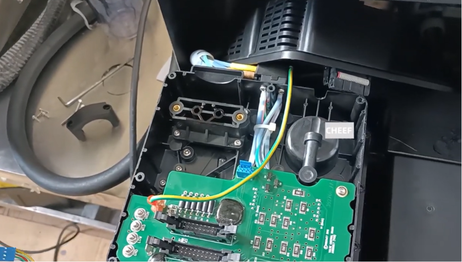
Within continuous inkjet (CIJ) systems, the internal pressure pump is the mechanical heart of fluid distribution. For the Videojet 1000 Series (comprising standard production models such as the 1210, 1220, 1510, and 1520), the main pump provides the constant volumetric displacement needed to pressurize ink and send it through the umbilical line to the nozzle plate.
Over thousands of hours of high-volume manufacturing, the inner gears or diaphragms of the internal pump head can wear down due to continuous mechanical stress and the chemically abrasive nature of industrial solvents. When a pump starts failing, the printer will suffer from severe pressure drops, erratic jet speeds, and poor droplet split-points.
Instead of paying for an entirely new modular ink core enclosure, field maintenance engineers can complete a targeted pump swap. This guide details the standard industrial maintenance steps required to safely disassemble, extract, and replace the pressure pump on Videojet 1000 Series machines.
Technical Indicators of Pump Degradation
Before dismantling the core housing, check for these explicit hardware and software warning signs that point to a worn-out pump mechanism:
- “Pump Speed Limit Exceeded” Alarms: The system motherboard attempts to ramp up pump RPM voltage to reach target operating pressure, eventually hitting a software ceiling.
- Fluctuating Ink Jet Velocity: Real-time telemetry shows the stream speed shifting erratically, leading to poorly formed or distorted text codes.
- Loud Internal Noise: Mechanical grinding, clicking, or high-pitched humming coming from inside the ink core block during a live jet loop.
Pre-Disassembly Isolation Protocols
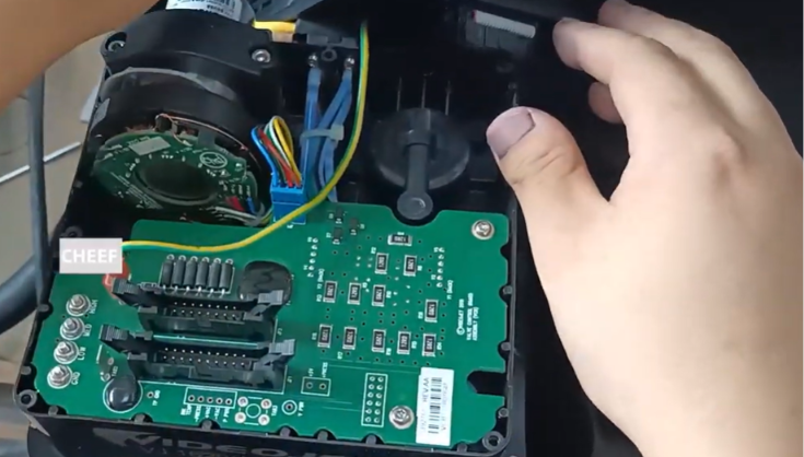
Working with components that are directly exposed to highly volatile, conductive fluids requires careful preparation to protect both the technician and the printer’s circuit board:
- Depressurize the Hydraulic System: Execute a standard “Stop Jet” sequence via the operational control interface. This runs an automatic line clear to drain remaining fluids and reduce backpressure.
- Complete Line Power Disconnection: Physically unplug the main AC power cord from the machine cabinet to avoid accidental shorts.
- Establish Grounding Safeguards: Put on an anti-static wrist strap hooked to an unpainted metal surface to safeguard the printer’s sensitive microprocessors from electrostatic discharge (ESD).
Phase 1: Disassembling the Core and Removing the Circuit Board
To reach the pressure pump, you must first clear away the top layers of protective shielding and disconnect the main electronic control board.
Step 1: Remove the Main Plastic Enclosure Lid
Locate the four retaining screws holding down the plastic outer cover shell of the ink core module. Undo the screws entirely, lift the cover lid straight off, and place it aside safely.
Step 2: Unplug the Data Ribbon Interface
Carefully decouple the wide, gray multi-pin ribbon data cable connected directly to the front face of the ink core circuit board. Pull straight up on the connector frame to prevent bending the delicate header pins.
Step 3: Clear the Auxiliary Wiring Contacts
- Unplug the remaining colored multi-wire connector blocks (such as the blue line interface) from their respective terminal plugs on the board.
- Unscrew and pull away the green and yellow ground safety wire linking the board plate to the frame ground.
Step 4: Displace the Electronic Board Assembly
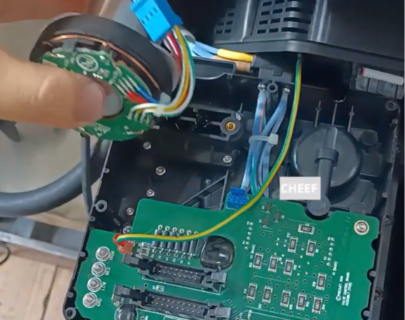
Unscrew the small structural mounting screws that secure the circuit board to the core’s plastic standoffs. Lift the board assembly carefully up and lay it gently over out of the workspace pocket. You can leave the secondary underlying cables attached while doing this.
Phase 2: Extracting and Replacing the Internal Pump Block
With the circuit board moved out of the way, the deep mechanical components of the ink core manifold—including the internal pump drive motor—are completely exposed.
Step 1: Release the Hydraulic Tube Couplers
Trace the fluid lines running directly into the input and output ports of the pump head. Use a small specialized wrench or gripping tool to undo the compression nuts or quick-connect fluid clips.
FIELD TIP: Have a lint-free industrial cloth ready immediately during this step to catch any small drips of stale ink trapped inside the pump head cavity.
Step 2: Unfasten the Pump Mounting Screws
Locate the primary retention screws anchoring the pump assembly block down into the lower plastic foundation of the ink core block. Use a matching hex wrench or screwdriver to back out the screws.
Step 3: Remove the Worn Pump Head
Lift the degraded pump module straight up out of its secure housing channel. Inspect the lower manifold bed to verify that no ancient ink buildup or debris is clogging the mounting area.
Step 4: Align and Install the Replacement Pump
Take the brand-new replacement pump assembly and lower it into the housing channel. Ensure the fluid inlet and outlet ports match the original flow direction of the hydraulic lines.
- Hand-start the mounting screws to avoid cross-threading, then tighten them down firmly.
- Reconnect the fluid delivery lines back to the pump head ports and tighten the compression fittings to form an airtight seal.
Phase 3: System Reassembly and Wiring Realignment
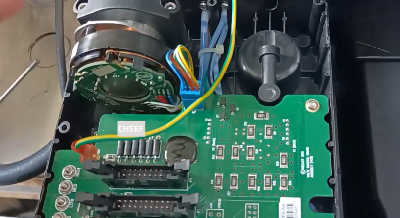
- Re-mount the Circuit Board: Reposition the ink core circuit board back flat over the plastic structural standoffs and secure it tightly with its original mounting screws.
- Reconnect Electronic Leads: Plug the colored auxiliary wire harness plugs back into their dedicated terminal pins. Reattach the green/yellow ground safety line wire securely.
- Secure the Data Ribbon: Press the wide gray communication ribbon cable firmly back down into its slot header until the locking clips click into place.
- Replace the Core Cover Shield: Re-set the outer plastic cover lid over the top of the assembly block and tighten down the 4 outer retention screws to isolate the internal electronics.
Post-Maintenance Startup and Validation Testing
Before handing the line back over to manufacturing operators, the service tech should verify fluid seals and line integrity:
- Execute a System Fluid Prime: Enter the service diagnostics screen and select the automated Pump Prime / Ink Fill routine. This draws fluid into the new lines and vents out trapped air pockets.
- Run a Real-Time Pressure Diagnostic: Turn on the jet loop and carefully monitor the pressure metrics on the interface panel. The pressure should quickly hit its target value and stay steady with zero fluctuations.
- Check for Structural Leaks: Use a flashlight to double-check the newly connected fluid tube joints inside the core deck to confirm there is zero wetness or fluid weeping.
Troubleshooting Reference Matrix
| Problem | Root Cause | Preventive Field Action |
| The new pump runs, but the machine struggles to build system pressure. | A fluid tube connection is loose, or air is leaking into a joint fitting. | Shut off the jet immediately, re-verify the input and output port compression fittings, and tighten them down another quarter-turn. |
| The interface shows an active pump error code immediately after boot up. | The main ribbon cable or internal pump power wires are loose. | Open the plastic cover lid and verify that the data ribbon cable and the pump harness plug are pushed entirely into their sockets. |
| The print has severe vertical text jitter or erratic spacing errors. | Trapped air pockets inside the new pump head are causing minor pressure surges. | Let the printer run its internal jet loop for an extra 10 to 15 minutes to fully bleed the hydraulic lines into the return gutter. |
Frequently Asked Questions
Q1: Is it possible to rebuild or fix the internal gears of a worn Videojet pump rather than buying a whole new pump kit?
While some third-party repair kits offer replacement internal gears or gear shafts, doing an internal rebuild requires advanced cleanroom settings. A single micron of dust or dried ink inside the gear mesh will cause rapid failure. Swapping the full modular pump block is much safer and delivers better long-term reliability for manufacturing environments.
Q2: Do different models within the Videojet 1000 Series use the exact same pressure pump?
Most baseline models like the 1210, 1220, 1510, and 1520 share the same standard pressure pump design. However, heavy-duty or micro-print machines (such as the 1610 or high-speed specialty units) may feature high-throughput pumps with unique electrical specs or different flow ratings. Always check the exact OEM part number stamped on the old pump body.
Q3: Why does the system configuration display a pump speed error if the new pump is working flawlessly?
Whenever you introduce a new mechanical pump block into the system, the internal resistance and flow dynamics will change slightly compared to the old, worn component. You may need to navigate to the technician’s calibration layout and run a software-driven Pump Speed Calibration sequence to update the baseline parameters stored on the main motherboard.
Watch the Full Video Tutorial:
This article summarizes the key points from our original video. Watching the full tutorial provides a clearer understanding of the procedures, demonstrations, and practical maintenance tips.
▶ Watch the full video below.
📺 Subscribe to the Cheef YouTube Channel to receive future maintenance guides, troubleshooting tutorials, product demonstrations, and industry updates.
