
Replacing the Electronic Solenoid Valves on Videojet 1000 Series CIJ Printers
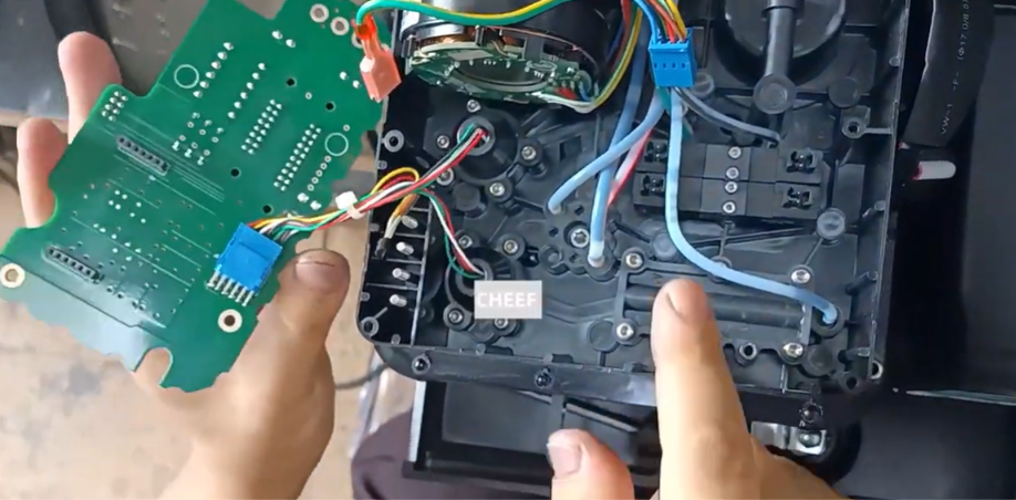
In industrial coding and marking setups, continuous inkjet (CIJ) printers like the Videojet 1000 Series (including the 1220, 1520, and 1610 models) rely on high-precision fluid management to maintain crisp prints. At the center of this fluid management system is the ink core module, which uses electronic solenoid valves to regulate the precise flow of ink and solvent makeup fluid.
When a solenoid valve begins to fail due to mechanical wear, debris buildup, or electrical coil burnout, the printer will experience critical fluid delivery issues. This can manifest as pressure drops, failure to start the ink jet, or ink-to-solvent mixing imbalances.
While many service providers recommend replacing the entire expensive ink core assembly, field engineers can save significant hardware costs by simply replacing the individual faulty electronic valve. This technical guide outlines the exact multi-phase process to safely extract and replace an electronic solenoid valve on the Videojet 1000 Series.
Technical Indicators of Solenoid Valve Failure
Before opening the core assembly, maintenance personnel should look for these systemic warning signs that point to a localized valve failure:
- Unstable System Pressure: The internal pump works harder, but pressure fluctuations persist due to a valve failing to seal completely or open fully.
- Inconsistent Ink Viscosity: A failure in the solvent selection valve blocks the automatic top-up line, causing the ink matrix to dry out and thicken.
- “Jet Starting” Timeouts: The control board attempts to open the main line valve, but an electrical breakdown in the valve coil stops fluid flow entirely.
Pre-Maintenance Safety Measures
Industrial inks and solvent fluids are highly volatile and conduct electricity easily. Before beginning the physical repair, follow these strict isolation rules:
- Initiate Clean Shutdown: Turn off the jet using the control panel interface to run the automated flush routine, clearing the lines of standing fluid and dropping system pressure.
- Cut Main Electrical Power: Disconnect the primary AC power line from the wall outlet to ensure a completely dead circuit.
- Use ESD Protection: Put on an anti-static wrist strap connected to a grounded metal surface to protect the delicate chip architectures on the core board from static shocks.
Phase 1: Accessing the Electronic Valve Block
The electronic solenoid valves sit directly underneath the main ink core circuit board (the ink core board). You must systematically remove the outer shields and the board to reach them.
Step 1: Remove the Protective Core Cover
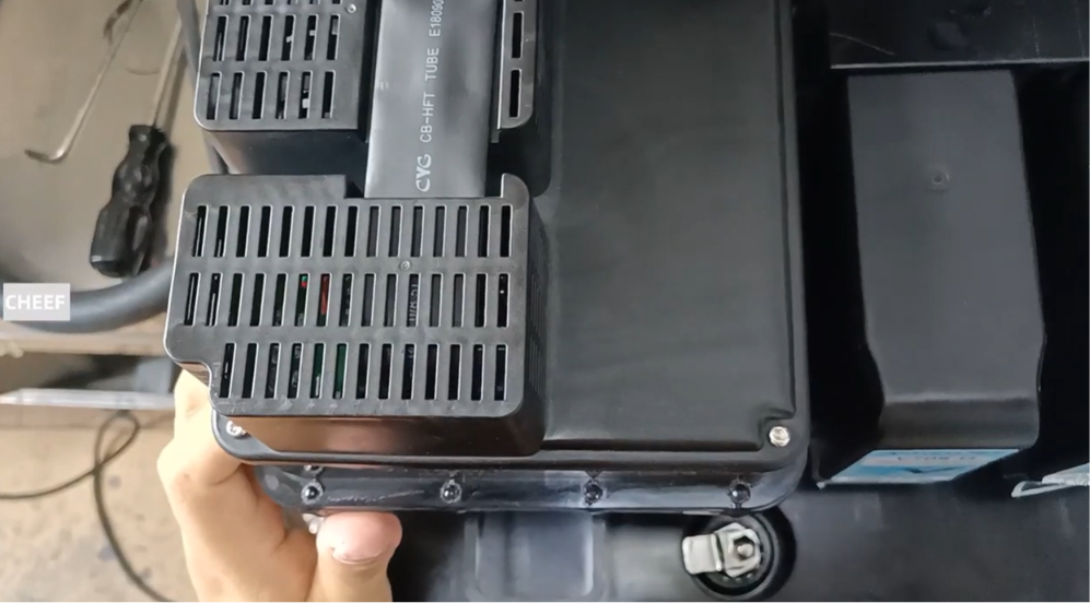
Unfasten and remove the four outer retention screws located on the plastic outer lid cover of the main ink core assembly. Lift the cover off and set it aside safely.
Step 2: Unplug the Main Communication Ribbon
Locate the wide, gray data ribbon cable plugged into the main circuit board header. Carefully pull the connector straight out of its slot to prevent bending any delicate pins.
Step 3: Loose and Disconnect Auxiliary Board Leads
- Unplug the main auxiliary wire harness plugs (such as the blue connector block) from their respective header pins.
- Unscrew and disconnect the green/yellow ground wire attached to the board’s chassis plate.
Step 4: Displace the Ink Core Board
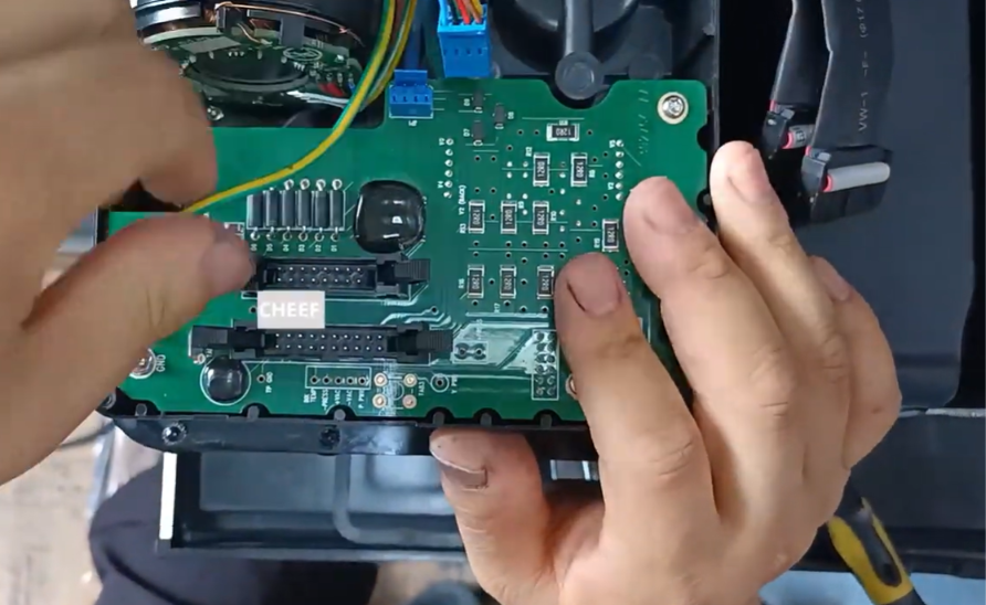
Remove the mounting screws that anchor the ink core board directly to the plastic core housing. Carefully lift the board up out of the assembly pocket and lay it over gently to the side. You do not need to pull out every single minor cable wire to do this.
Phase 2: Removing and Installing the Solenoid Valve
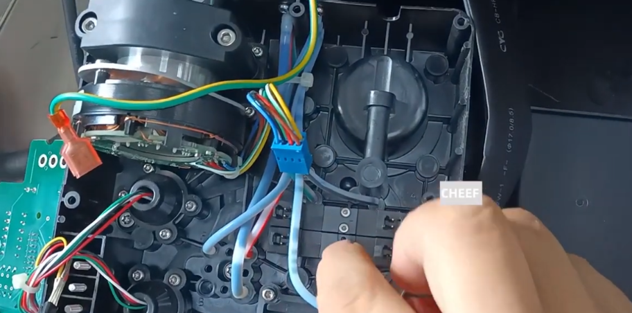
With the circuit board moved out of the way, the bank of modular electronic valves is fully exposed.
Step 1: Extract the Damaged Valve
Locate the specific valve showing errors in your diagnostics. Using a 1.5mm hex key or specialized hex screwdriver, loosen and remove the two retaining screws securing the valve to the core’s fluid manifold. Pull the faulty valve straight up and out of its seating slot.
Step 2: Align and Install the Replacement Valve
Take the new replacement valve and verify that its integrated rubber O-ring seals are seated correctly in their grooves.
CRITICAL DIRECTIONAL ALIGNMENT NOTE: When inserting the new valve into the manifold slot, you must ensure that the side of the plastic valve housing with the printed text/words faces directly outward toward you. Installing the valve backwards will reverse the fluid ports, blocking flow and risking pressure damage to internal diaphragms.
Step 3: Secure the Valve Assembly
Push the valve firmly down into its manifold seat. Reinsert the two mounting screws and tighten them down evenly using your 1.5mm hex tool. Avoid over-tightening, as too much force can strip the plastic threads inside the manifold core body.
Phase 3: Reassembling the Ink Core Module
- Reposition the Core Board: Lay the main circuit board back flat over the internal valve assembly, ensuring all screw holes line up with the plastic standoffs. Secure it using the original board screws.
- Reconnect the Wiring Assemblies: Plug the auxiliary connector blocks back into their header pins and tightly secure the green/yellow ground safety wire back to its terminal point.
- Re-engage the Ribbon Cable: Insert the gray data ribbon cable back into its slot on the core board, making sure the connector clips click firmly into place.
- Close the Core Shell: Set the plastic core lid back over the top assembly and screw down the 4 outer cover screws to seal the internal electronics from future fluid splashes or vapor exposure.
Operational Validation Testing
Before jumping back into live production, field engineers must verify that the new valve functions correctly under pressure:
- Run a Fluid Prime Sequence: Use the diagnostic menu to manually prime the ink and makeup fluid lines. This forces air pockets out of the new valve chamber.
- Inspect closely for Micro-Leaks: Watch the base of the newly installed valve for any signs of wetness or ink weeping, which would indicate a misaligned O-ring seal.
- Confirm Diagnostic Telemetry: Verify that the main user interface screen does not display any remaining fluid distribution errors or valve circuit alarms.
Field Maintenance Reference Matrix
| Problem | Root Cause | Preventive Field Action |
| Valve leaks from its base right after installation. | The valve was installed backward, or the O-ring seals twisted out of place. | Remove the valve, check that the printed text faces outward toward you, and make sure the O-rings sit completely flat before screwing it down. |
| The printer throws an error code for the valve immediately on boot. | The main communication ribbon or auxiliary wires are loose. | Open the plastic cover lid and ensure the wide gray ribbon cable is pressed all the way into its socket. |
| Rapid valve wear or premature internal clogging. | Contaminated ink or using poor-quality third-party fluids. | Always flush the fluid core using certified clean solvent and stick to high-grade industrial inks. |
Frequently Asked Questions
Q1: Can I replace a valve while the printer is still turned on if the ink jet is stopped?
Absolutely not. The solenoid valves operate under constant electronic control from the motherboard, and the core board carries live currents. Swapping a valve while powered on can cause immediate electrical shorts that permanently ruin the ink core board or create a sudden pressurized spray of ink.
Q2: Are all the solenoid valves inside a Videojet 1000 Series ink core completely identical?
Physically, the individual valves share the same base structure and layout across the bank. However, they perform very different individual roles—such as controlling ink delivery, managing top-up makeup lines, or running system flushes. Always verify you are replacing the exact valve flagged by your diagnostics.
Q3: What should I do if the valve screws are stuck or won’t break free during removal?
Because industrial inks can dry like a strong glue, a tiny drop of fresh washdown solvent can be applied directly to the screw heads. Let it sit for a minute or two to dissolve any dried ink binders holding the threads before trying to back the screws out with your 1.5mm hex tool.
Watch the Full Video Tutorial:
This article summarizes the key points from our original video. Watching the full tutorial provides a clearer understanding of the procedures, demonstrations, and practical maintenance tips.
▶ Watch the full video below.
📺 Subscribe to the Cheef YouTube Channel to receive future maintenance guides, troubleshooting tutorials, product demonstrations, and industry updates.
