
Videojet 1000 Series Ink Core Board Replacement and Repair Guide
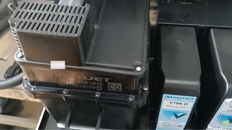
In modern packaging and labeling environments, the Videojet 1000 Series (including models like the 1210, 1220, 1510, 1520, and 1610) relies heavily on a modular modular fluid system known as the Ink Core. Managing the distribution of ink, makeup fluid, and filtration, the ink core works hand-in-hand with an attached internal electronic control board—the ink core board.
When component failure, physical fluid ingress, or telemetry communication errors strike this specific board, a full ink core replacement is often recommended by OEMs. However, for B2B distributors, field service organizations, and cost-conscious plant operations, changing out or repairing just the internal ink core board is a highly viable, cost-effective alternative.
This industrial manual provides field engineers with the technical procedures required to safely extract, replace, and verify the circuit board assembly on a standard Videojet 1000 Series ink core.
Technical Indicators: When to Replace the Core Board
Unlike mechanical blockages or worn pump cylinders, electrical issues with the ink core board show up via distinct system telemetry flags on the main user interface screen:
- Core Communication Error: The printer completely loses tracking data from the ink core module, preventing jet startup.
- Faulty Temperature/Pressure Sensor Readings: The board fails to interpret signals from internal thermistors or pressure transducers, prompting constant out-of-bounds errors.
- Smart Chip Recognition Failure: The system refuses to validate genuine ink or solvent cartridge chips due to a localized processing break on the core bus.
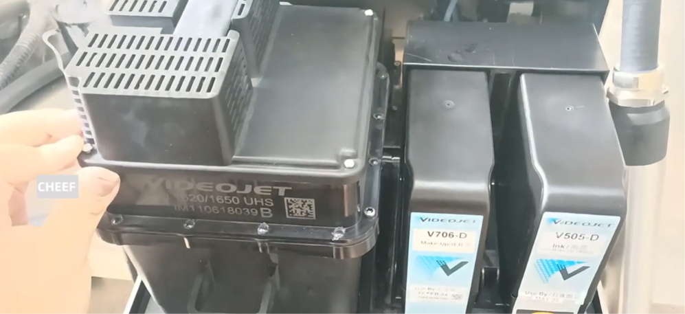
Pre-Replacement Safety Protocol
Industrial continuous inkjet fluids are highly volatile and electrically conductive. Before attempting any board swap, follow these strict isolation guidelines:
- Perform a Managed Shutdown: Turn off the printer via the control panel interface to ensure all automated fluid lines are completely clear and pressure is fully decompressed.
- Complete Electrical Isolation: Disconnect the primary AC power cable from the main wall outlet.
- Ground the Environment: Put on an anti-static wrist strap and connect it to a grounded metal point to avoid electrostatic discharge (ESD) from damaging the microchip arrays.
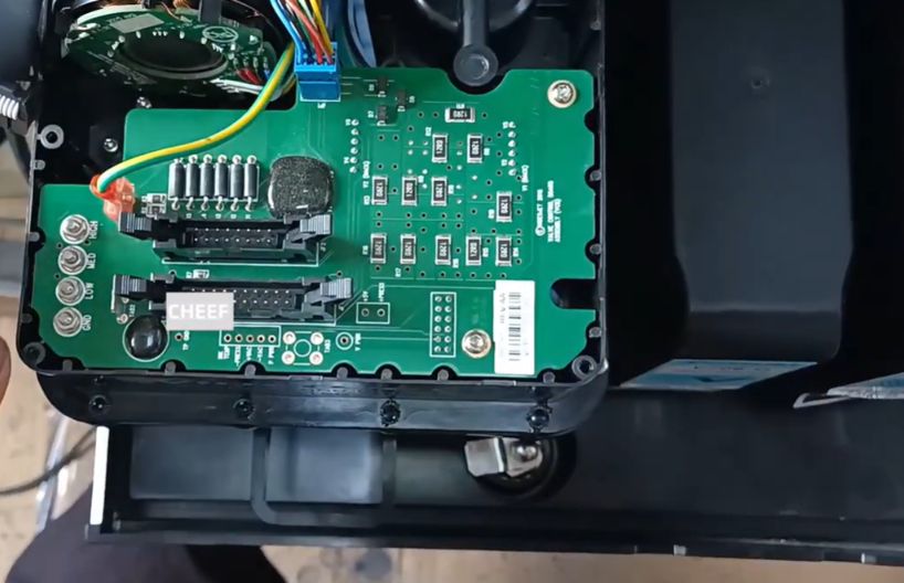
Step-by-Step Ink Core Board Removal and Installation
Follow this precise sequence to successfully complete the hardware swap without compromising the surrounding seals.
Step 1: Open the Enclosure and Extract the Ink Core Assembly
Undo the cabinet door latch to access the fluid compartment. Disconnect the main wire harness plugs feeding from the primary motherboard down to the ink core. Release the physical core locking levers and pull the entire ink core block straight out of the machine housing.
Step 2: Unfasten the Board Protective Shield
Locate the electronic board compartment on the back side of the extracted core block. Use a cross-recess screwdriver to remove the mounting screws holding the protective cover or outer housing piece over the board area. Set the screws aside securely.
Step 3: Disconnect Internal Sensor Leads
Carefully unplug the small internal wire connectors and ribbon lines linking the internal ink core pump, pressure sensors, and valves directly to the board’s header pins. Take note of their exact routing or snap a picture for reference during reassembly.
Step 4: Extract the Faulty Circuit Board
Remove the small retaining screws anchoring the circuit board directly to the plastic core chassis. Lift the old board straight out of its mounting pocket, taking care not to scrape or nick the underlying seals or wiring.
Step 5: Mount and Align the Replacement Board
Position the new replacement board into the core’s mounting pocket, ensuring all screw holes line up perfectly with the plastic standoffs. Hand-tighten the retaining screws gently; over-tightening can easily crack the multilayer printed circuit board (PCB).
Step 6: Reconnect Wires and Reassemble
Plug all the internal sensor leads and pump wire connectors back into their respective header pins on the new board. Reinstall the protective outer cover shield and tighten down its screws. Slide the completed ink core module back into the printer housing, lock the levers in place, and plug the main wiring harnesses back together.
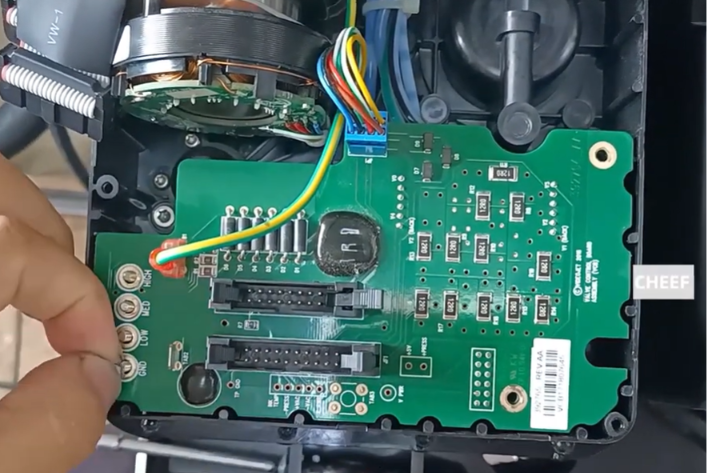
Post-Installation Commissioning and Test Routine
Once everything is put back together, the new core board must be properly introduced to the printer’s primary operating system.
- Power Up and Monitor Diagnostics: Reconnect the main power line and turn on the machine. Watch the screen carefully during the boot sequence to ensure no communication faults show up.
- Read the New Core Identity: Navigate into the service diagnostic menu. Verify that the system successfully recognizes the new board assembly along with its internal serial tracking and runtime metrics.
- Conduct a Pressure and Flow Test: Run a test jet cycle to ensure the new board accurately monitors and adjusts internal pump speeds and system pressure fields back to target production specs.
Preventative Practices for B2B Supply Managers and Technicians
| Operational Threat | Resulting Issue | Preventative Strategy |
| Fluid Seepage/Spills | Ink or cleaning solvent drips onto the board during cartridge swaps, causing short circuits. | Always wipe the cartridge bays down instantly if any fluids leak. Ensure the protective board shield is firmly screwed down. |
| High Heat Accumulation | Elevated ambient operating temperatures bake the core board components over time. | Keep the cabinet air filters clean to maintain proper airflow and cooling across the electronics. |
| Improper Wire Tucking | Internal wires get pinched or crimped during board cover installation. | Carefully route and tuck all internal sensor leads away into their designated plastic channels before closing up the cover. |
Frequently Asked Questions
Q1: Do I need to reprogram or re-flash firmware when installing a new ink core board?
In most cases, no. Certified replacement boards come pre-loaded with the core operational parameters required to talk directly with the main Videojet 1000 Series motherboard. The main unit will automatically detect the module configuration on startup.
Q2: Can a damaged or shorted ink core board ruin the printer’s main motherboard?
Yes. If the core board has a severe short circuit from a fluid spill, it can potentially draw too much power back through the data bus lines and blow communication components or fuses on the main control motherboard. Always isolate power immediately if a fluid leak is found near the electronics block.
Q3: Is it possible to swap boards between a Videojet 1220 and a 1520 printer core?
While the boards look physically similar, they often carry distinct software and hardware configurations depending on the specific machine’s features, line speeds, and fluid setups. Always cross-reference the exact part number labeled on the board itself to guarantee perfect compatibility.
Watch the Full Video Tutorial:
This article summarizes the key points from our original video. Watching the full tutorial provides a clearer understanding of the procedures, demonstrations, and practical maintenance tips.
▶ Watch the full video below.
📺 Subscribe to the Cheef YouTube Channel to receive future maintenance guides, troubleshooting tutorials, product demonstrations, and industry updates.
