
Print Module & Nozzle Deck Replacement for Videojet 1000 Series Printheads
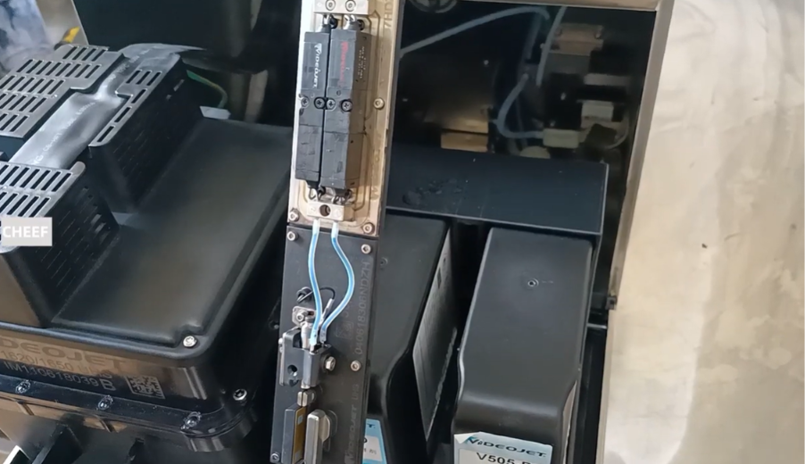
In continuous inkjet (CIJ) technology, the printhead is where the actual coding magic happens. For the Videojet 1000 Series (including the 1210, 1220, 1510, 1520, 1610, and 1620), the Print Module—often referred to as the print deck or nozzle manifold assembly—is the high-precision core inside the printhead structure. It integrates the drop generator, micro-nozzle (typically 60 or 70 microns), the drive piezo crystals, and the printhead modulation valves into a singular, unified deck.
Over thousands of hours of high-speed coding, the physical print module experiences extreme micro-vibrations and constant fluid shear. If internal ink deposits harden within the manifold channel, or if the internal sapphire nozzle disk gets chipped or unseated, the drop formatting process breaks down. This results in severe code clipping, poor modulation readings, and frequent stream stability faults.
Swapping out the old modular print deck is a highly cost-effective alternative to discarding the entire printhead and umbilical hose assembly. This manual provides a concise, professional field procedure to extract the degraded print module and install a fresh one.
Technical Indicators for Print Module Replacement
Field service technicians should target the print module for replacement when encountering the following systemic operational patterns:
- Irrecoverable Stream Misalignment: The ink stream shoots crookedly out of the drop generator, completely missing the gutter slot even after deep physical cleaning and ultrasonic nozzle washdowns.
- Faulty Ink Modulation Readouts: The printer logs persistent “Modulation Calibration” errors or cannot properly form drops because the internal crystal transducer inside the block has degraded.
- Persistent Un-flushable Clogs: Microscopic sediment or dried fluid remains permanently wedged behind the sapphire nozzle orifice, causing the jet to repeatedly back up or spray violently inside the printhead cover.
Pre-Maintenance Safety and Cleanliness Protocols
WARNING: UNCOMPROMISING CLEANLINESS REQUIRED
The internal passages of the print module are manufactured to micron-level tolerances. A single speck of airborne plant dust or lint introduced during assembly can instantly brick the new module.
- Purge and Stop the System: Run a thorough printhead clean-and-flush cycle with makeup solvent. Shut down the fluid loop completely via the control panel interface.
- Disconnect Main AC Power: Unplug the machine’s primary power cord from the wall outlet to neutralize any active circuit boards or high-voltage lines running down the umbilical.
- Clean the Exterior Workspace: Thoroughly wash down the entire printhead assembly with solvent and blow it 100% dry using clean, oil-free compressed air before loosening a single screw. Ensure your hands or workspace are free of debris.
Step-by-Step Print Module Deck Replacement Procedure
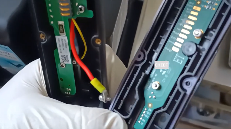
The print module sits inside the protective stainless steel printhead chassis, linked directly to the main fluid lines of the umbilical hose and the electrical distribution board.
Step 1: Open the Printhead Enclosure
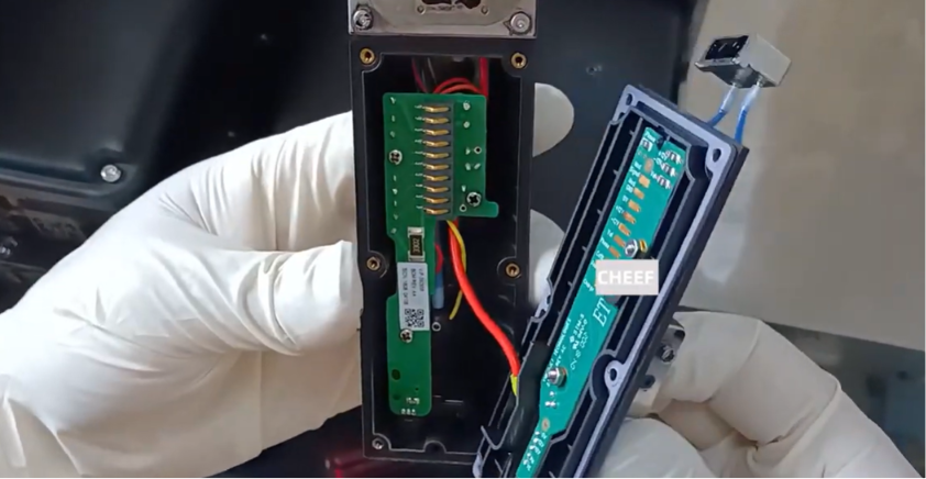
Remove the outer stainless steel printhead cover plate. Locate the internal module retention frame screws on the side or rear of the printhead skeleton and back them out using a precision hex tool or cross-recess screwdriver.
Step 2: Disconnect the Fluid Line Manifold
The print module features quick-sealing fluid ports matching the ink and makeup lines feeding from the printer’s main core.
- Unfasten the retaining bracket securing the feed line tubes.
- Carefully detach the fluid quick-connect links or block lines from the rear port of the module deck. Use a lint-free wipe to catch any small drops of lingering solvent or ink.
Step 3: Unplug Electrical Pins and Valves
- Disconnect the wiring harness leading to the micro-solenoid head valves (typically the 19V or 24V pintle control valves mounted directly on top of the module deck).
- Carefully disconnect the drive signal wire pins that deliver electrical pulses to the internal drop-generating crystal.
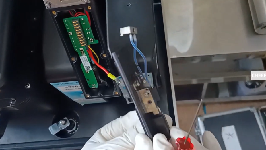
Step 4: Extract the Damaged Print Module Deck
Gently lift the print module deck out of the printhead housing frame. Pull it straight out to avoid twisting or scratching any nearby deflector plates or charging electrode blocks.
Step 5: Mount the New Print Module Assembly
Take the new replacement module (ensuring you match the exact nozzle size, such as 60-micron or 70-micron, required for your production line setup).
- Guide the module carefully into the printhead frame, ensuring all locating tabs align with the chassis housing.
- Hand-tighten the primary mounting screws to lock the deck securely into place.
Step 6: Secure Fluid and Electrical Interconnects
- Push the main fluid line connections firmly back into the module’s input manifold ports until they sit flush, then secure the line retaining clip.
- Reconnect the control board wiring connectors to the head valves and plug in the drive crystal signal line pins securely.
Post-Replacement Alignment and Calibration Sequence
- Inspect Stream Centering: Turn on the printer and engage the ink jet. Look through a high-power magnifying loop to ensure the fluid jet shoots perfectly straight down the center line of the charge tunnel and cleanly into the middle of the suction gutter.
- Calibrate Modulation Profiles: Navigate to the service diagnostic menu on the display console. Run the automatic drop modulation calibration cycle. This allows the printer to tune its signal voltage to the specific resistance of the new crystal.
- Run a Phase & Print Test: Execute a multi-line trial print run onto film or cardboard labels. Check for sharp character margins and clean drop separation, confirming that the new print module is perfectly synchronized with the printer’s timing system.
Field Maintenance Reference Matrix
| Operational Symptom | Root Cause | Corrective Field Action |
| Ink stream sprays or clips the edge of the charge tunnel on initial startup. | The print module is slightly misaligned in its mounting cradle, or the nozzle face is dirty. | Loosen the module mounting screws, re-center the deck body manually, and gently retighten them. Wash the nozzle plate with fresh cleaning fluid. |
| The printhead reports a “No Jet Detected” fault despite fluid flowing. | The ink stream is shooting crookedly and missing the gutter sensor loop entirely. | Stop the jet immediately. Readjust the module positioning mechanical screws to guide the fluid stream dead-center into the gutter entry hole. |
| New module is installed, but the head valves fail to open or click. | The valve wiring harness connector is loose or plugged in backward. | Shut down power, verify the wire colors match your original schematic layout, and press the connector fully home. |
Frequently Asked Questions
Q1: Can I replace just the sapphire nozzle disk instead of the whole print module deck?
While the nozzle disk can technically be separated on certain non-standard components, the factory-assembled print module is pre-bonded and sealed to prevent leaks at extremely high pressures. Attempting to replace just the sapphire tip in a standard plant workshop often ruins the fluid seal, leading to persistent ink leaks inside the head. Replacing the unified deck is the standard industry practice.
Q2: What is the primary operational difference between a 60-micron and a 70-micron print module?
A 60-micron module produces smaller ink droplets, making it ideal for sharp, ultra-fine text on small components or high-density expiration dates. A 70-micron module creates larger droplets, which deliver higher-contrast codes on highly absorbent packaging materials or rough surfaces. You must update your printer’s software profile to match whichever nozzle size you install.
Q3: Why is positive head air so important right after installing a new print module?
Positive head air introduces a gentle stream of filtered air into the printhead housing, creating positive pressure that pushes outward. This prevents airborne plant dust, fibers, and moisture from settling inside the charge tunnel or onto the sensitive nozzle plate of your brand-new module during live production runs.
Watch the Full Video Tutorial:
This article summarizes the key points from our original video. Watching the full tutorial provides a clearer understanding of the procedures, demonstrations, and practical maintenance tips.
▶ Watch the full video below.
📺 Subscribe to the Cheef YouTube Channel to receive future maintenance guides, troubleshooting tutorials, product demonstrations, and industry updates.
