
Essential Field Precautions for Videojet Maintenance: Ink Cores, Valve Modules, and Printheads
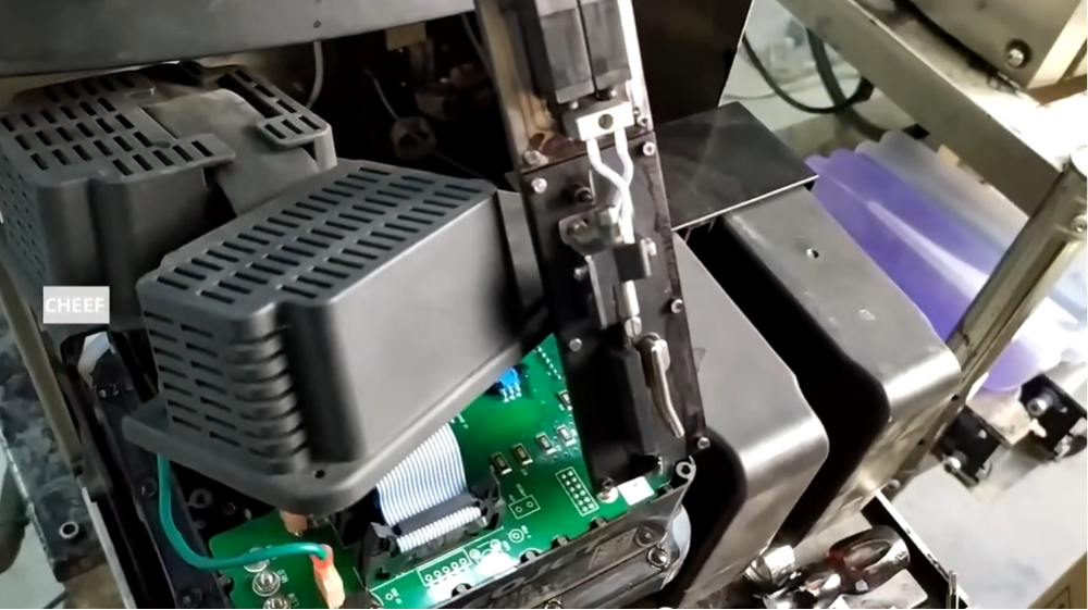
Maintaining high-speed Continuous Inkjet (CIJ) systems demands strict adherence to technical parameters. When field technicians or distribution engineers service Videojet 1000-series printers, component swaps must be executed with precision. A single misplaced gasket or an unverified signal path can result in pressure drops, ink stream misalignment, or motherboard faults.
This technical briefing outlines critical field precautions required when replacing the main ink core, the modular valve assembly, and the printhead module to ensure immediate system recovery and optimal print quality.
Critical Safety and Static Protocols Before Servicing
Industrial marking fluids rely on volatile organic compounds (VOCs) like Methyl Ethyl Ketone (MEK) or ethanol, which carry high flammability risks. Additionally, the printer’s internal control boards are highly sensitive to Electrostatic Discharge (ESD).
- Isolate Electrical Power: Always initiate a controlled software shutdown sequence before disconnecting the main AC power cord. Never hot-swap fluid modules while the motherboard is energized.
- ESD Grounding: Technicians must wear a grounded anti-static wrist strap connected to the printer’s chassis ground. Static electricity can irreparably fry the control logic on the motherboard or printhead driver boards.
- Solvent Management: Ensure the surrounding work area is well-ventilated. Use clean, lint-free wipes for all maintenance; standard paper towels shed microscopic fibers that will immediately clog the nozzle or gutter system.
Technical Precautions for Main Ink Core and Pump Installation
The main ink core assembly acts as the hydraulic engine of the printing system. Proper physical alignment and airtight sealing during installation are paramount.
Mechanical Gaps and Air Entry
The joint interface on the replacement ink core must be fitted tightly with absolutely no visible gaps against the main chassis. If the assembly is loose or misaligned, the vacuum pump will draw ambient air into the ink loop rather than drawing fluid. This leads to erratic system pressure readings, foam generation in the mixing tank, and eventual “Pressure Low” system faults.
Pump Seating and Alignment
The circulation pump must slide fully into its designated internal slot. Leaving the pump partially seated or tilted changes the mechanical load on the drive motor, causing premature pump wear and throwing off the automated ink circulation calibration loop.
Valve Module Replacement Checklist
The individual solenoid valves regulate the precise routing of ink, makeup fluid, and gutter return vacuum paths. They require extreme care during mechanical assembly and digital testing.
Component Seating and Internal Washers
When swapping out a valve module, technicians must verify the presence and seating of the small internal elastomer sealing washers. If a single washer falls out or becomes pinched during installation, it will cause an internal pressure cross-leak or fluid weeping. This directly disrupts the fluid viscosity monitoring system.
Electrical Verification and the Manual Test
Physical mounting is only half the process. Once the valve module is mechanically secured, technicians should enter the advanced service menu to perform a diagnostic valve actuation check.
Listen closely for a clear, crisp acoustic “click” or ringing sound from the solenoid. If a valve fails to ring, it typically indicates a physical alignment issue within the seat or an incomplete electrical connection rather than a defective part.
Print Module and Stream Calibration Practices
Installing a new print module or adjusting printhead internals introduces structural variables that require immediate manual tuning.
Addressing Initial Recovery Faults
It is common for a newly installed print module to throw a “recovery fault” or display a canted ink line during its initial startup cycle. Because the fluid lines inside a new module are dry, the initial pressure surge can cause minor stream instability until air is fully evacuated.
Ink Stream Realignment Procedure
If the ink line shoots off-center after installation, it must be manually calibrated. Use the precise adjustment screw located on the printhead assembly to physically reposition the drop generator until the ink stream hits the absolute center of the recycling gutter.
Nozzle and Gutter Diagnosis
If adjusting the alignment screw fails to true up a crooked stream, the issue is likely a partial physical blockage rather than a mechanical misalignment. Inspect the micro-nozzle plate for dried ink deposits or lint fibers. If debris is found, perform a thorough wash down using the designated cleaning solvent, blow it dry with low-pressure air, and restart the stream test.
Common Field Issues and Corrective Actions
| Component Issue | Root Cause | Corrective Action |
| E01 Ink System Pressure Fault | Air entering the lines via a loose ink core joint. | Remove the core, inspect the bottom sealing face, re-seat flush against the chassis, and hand-tighten structural screws. |
| Fluid Seepage Behind Valve Block | Missing or unseated internal sealing washer during replacement. | Uninstall the valve module, verify all internal washers are perfectly flat in their channels, and reinstall. |
| Ink Stream Deflection (Crooked Line) | Microscopic debris on nozzle or incorrectly adjusted printhead screw. | Clean the nozzle plate thoroughly with solvent. If unresolved, use the alignment screw to center the stream in the gutter. |
| Gutter Vacuum Failure | Clogged lines or debris accumulation inside the recycling tank. | Detach the recycling lines and flush them with warm cleaning solvent using a service syringe to clear restrictions. |
Target Industrial Applications
High-Speed Beverage Bottling
Beverage plants run automated lines that cannot tolerate unplanned stops. Preventing air leaks during core swaps ensures the printer maintains stable viscosity despite ambient humidity shifts near washing and filling areas.
Automotive Parts Marking
Automotive components often require specialty pigmented or high-adhesion inks. Ensuring the valve modules are clicking and sealing correctly prevents heavy particulates from settling out in the valve channels, which would otherwise ruin the contrast of part number codes.
Frequently Asked Questions
Why does my printer say “Low Pressure” after I just installed a brand-new ink core?
A new ink core is entirely empty of fluid. If the system is not primed, the software assumes a leak exists because pressure does not build instantly. You must run the system “Ink Line Prime” routine through the service menu to fill the internal chambers and push out trapped air.
What happens if I accidentally reverse the electrical connectors on the valve module?
The printer’s software will route fluid down the wrong internal pathways—for example, pumping solvent into the ink stream or vice versa. This will quickly ruin ink viscosity and throw a system error. Always label or photograph the valve wires before disconnecting them.
Can I clean a clogged printhead nozzle with a metal needle or wire?
No. The nozzle orifice is cut to a precise micrometer specification (typically 60 or 70 microns). Using any hard metal tool will distort or scratch the jewel or plate, permanently ruining drop formation and requiring a full module replacement. Use only approved wash solvents and low-pressure suction or air to clear clogs.
Watch the Full Video Tutorial:
This article summarizes the key points from our original video. Watching the full tutorial provides a clearer understanding of the procedures, demonstrations, and practical maintenance tips.
▶ Watch the full video below.
📺 Subscribe to the Cheef YouTube Channel to receive future maintenance guides, troubleshooting tutorials, product demonstrations, and industry updates.
