
Technical Framework: Videojet 1000 Series Pressure Pump Overhaul and Replacement Protocol
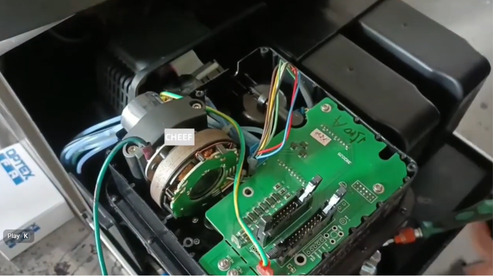
The high-pressure fluid pump is the mechanical heart of the Videojet 1000 Series continuous inkjet (CIJ) printing system. It generates the precise hydraulic force required to push ink through the core manifold and out of the micro-nozzle orifice at velocities sufficient for clean drop modulation. Operating continuously in heavy industrial environments, the internal seals and gears of the pump assembly eventually experience mechanical wear, resulting in pressure fluctuations, fluid weeping, or motor stall faults.
For maintenance engineers, technical supervisors, and industrial component distributors, mastering the correct extraction and seating process for this critical pump module is essential for ensuring long-term systemic uptime and precise fluid circulation.
Technical Insights: The Internal Pump Interface
The pressure pump on the Videojet 1000 series (including the 1210, 1510, 1610, and related platforms) sits directly beneath the electronic chassis interface, linking to the main ink core housing. The pump relies on a tight physical alignment and a dedicated series of rubber O-rings to maintain a vacuum-sealed connection with the fluid distribution block.
When replacing this assembly, technicians must treat it not just as a mechanical bolt-on item, but as a sensitive hydraulic and electrical component. A slight misalignment during seating can crimp internal seals, causing ambient air to leak into the ink stream, which immediately triggers automated system errors or causes erratic ink drop placement on the line.
Step-by-Step Disassembly and Extraction Procedure
Before initiating maintenance, power down the printer completely, disconnect the main AC electrical feed, and equip yourself with an anti-static wrist strap, lint-free cloth wipes, a metric Allen hex key set, and clean wash solvent.
Phase 1: Isolation and Shroud Removal
- Open the primary cabinet door to access the fluid compartment layout.
- Remove the structural chassis screws securing the upper electronics shielding cover and lift away the protective shroud.
- Locate the primary motherboard connection array directly above the pump deck. Disconnect the auxiliary power harness and multi-pin communications plugs to clear a line of sight to the lower pump body.
Phase 2: Unfastening the Mechanical Retainers
- Identify the structural mounting block screws securing the pump assembly to the lower ink core chassis rails.
- Using the correct metric hex key, loosen the retention screws in an alternating pattern to prevent twisting stress on the underlying alignment frame.
- Carefully slide back the mechanical locking bracket holding the pump head flush against the fluid manifold block.
Phase 3: Extraction and Seal Inspection
- Grip the pump body firmly and pull it straight out of its mounting pocket along the axis of the rails. Do not twist or rock the unit excessively during extraction, as this can score the internal metal seating faces.
- Once extracted, immediately place the old pump on a clean service tray.
- Inspect the internal fluid ports on the manifold for any remaining rubber seal fragments, dried ink sediment, or scoring that could compromise the seating of the new replacement unit.
Installation and Reassembly Protocol
Phase 1: Pre-Lubrication and Seating
- Unbox the new replacement pump and verify that the part number matches the system’s chemical ink requirements (e.g., standard vs. high-pigment options).
- Lightly lubricate the new integrated interface O-rings with a thin film of clean makeup fluid or approved service lubricant to prevent pinching during insertion.
- Align the pump shaft carefully with the internal drive coupling within the chassis pocket.
- Push the pump module straight in until the front mounting plate sits completely flush against the face of the fluid block with zero visible gaps.
Phase 2: Torquing and Electrical Reconnection
- Hand-thread the structural retention screws through the mounting frame to ensure correct thread alignment.
- Tighten the screws securely using a balanced cross-pattern sequence to ensure even pressure distribution across the internal gaskets.
- Route the power harness neatly away from any sharp metal edges and reattach the primary multi-pin communication plug to the motherboard port.
- Reinstall the upper protective shroud and torque the remaining outer cabinet frame screws firmly into place.
Troubleshooting Common Installation Errors
| Post-Installation Symptom | Probable Technical Root Cause | Corrective Field Action Plan |
| “Pump Motor Overload” Error on Boot | Misalignment between the pump shaft and the internal drive coupling causing mechanical binding. | Loosen the mounting screws, back the pump out slightly, rotate the shaft gently to align the coupling, and re-seat flush. |
| System Fails to Build Pressure | Ambient air leaking into the fluid stream via a pinched or unlubricated interface O-ring. | Extract the pump module, replace damaged rubber gaskets, lubricate with makeup fluid, and reinstall. |
| Fluid Weeping at Pump Base | Uneven torque applied to the structural retention screws during reassembly. | Loosen the mounting screws completely and re-tighten them in an alternating, balanced cross-pattern. |
Operational Preventative Maintenance
- Enforce Clean Assembly Areas: Even a single airborne fiber or microscopic speck of grit caught on an O-ring during installation can prevent a perfect seal, leading to micro-leaks that drop fluid pressure over time. Always clean the extraction zone with wash solvent before sliding the new pump into place.
- Perform a Forced System Prime: Never attempt to start the primary printing jet immediately after installing a dry pump module. Navigate to the maintenance user interface and execute a manual “Ink Line Prime” loop. This draws fresh fluid through the pump head, lubricating the internal gears before they spin at high operational speeds.
Frequently Asked Questions
Can I rebuild the internal gears of a worn Videojet pump rather than replacing the whole module?
While minor seal replacements are possible in a cleanroom workshop environment, field rebuilding of internal pump gears is generally not recommended for high-volume production lines. The micron-level tolerances required to maintain consistent system pressure are difficult to replicate in the field, making a complete factory-calibrated module replacement the safest choice to ensure production uptime.
How can I tell if a pressure fault is caused by a bad pump or a clogged ink core filter?
Run a diagnostic pressure stability test through the system menu. If the pump motor speed fluctuates wildly while trying to maintain a steady pressure reading, the pump or its drive coupling is likely worn. If the pump motor speed remains steady but high, while actual fluid pressure remains low, the issue is typically a clogged internal filter within the ink core block.
What happens if I accidentally operate the new pump dry during startup?
Running a new pressure pump completely dry for more than a few seconds generates rapid friction heat between the high-precision internal gears. This can scuff the internal components and prematurely degrade the main shaft seals. Always pre-prime the system or add a small amount of clean fluid to the intake path before running the motor.
Watch the Full Video Tutorial:
This article summarizes the key points from our original video. Watching the full tutorial provides a clearer understanding of the procedures, demonstrations, and practical maintenance tips.
▶ Watch the full video below.
📺 Subscribe to the Cheef YouTube Channel to receive future maintenance guides, troubleshooting tutorials, product demonstrations, and industry updates.
